

Heat exchanger and manufacture method for the same
A manufacturing method and heat exchanger technology, which can be applied to heat exchange equipment, heat exchanger shells, lighting and heating equipment, etc., and can solve problems such as fluid space leakage
- Summary
- Abstract
- Description
- Claims
- Application Information
AI Technical Summary
Problems solved by technology
Method used
Image

Examples
no. 1 example
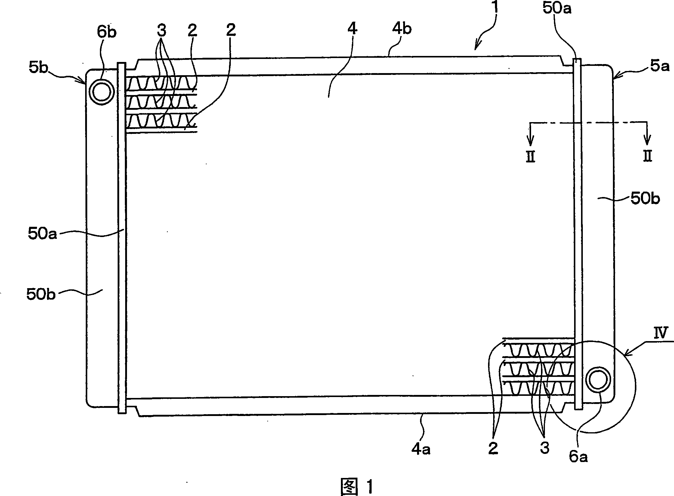
[0035] A heat exchanger according to a first embodiment of the present invention will be described below with reference to FIGS. 1 to 9 . The heat exchanger can be suitably used as, for example, a radiator 1 of a vehicle. The radiator 1 may be arranged in an engine room of a vehicle to cool a fluid (for example, cooling water) by air blown by a blower.
[0036] As shown in Figure 1, the radiator 1 is provided with: a core unit 4, the core unit 4 includes a plurality of conduits 2 and a plurality of cooling fins 3; two side plates 4a, 4b; and two header tanks 5a and 5b.
[0037] The conduit 2 is formed of a flat tube in which cooling water from the engine flows. The conduit 2 can consist of a light metal with high thermal conductivity, for example aluminum. In this embodiment, the conduit 2 consists of a clad material whose surface (front and / or rear) is covered with a filling material.
[0038] Fins 3 are attached to the outer surface of the duct 2 to increase the heat tra...
no. 2 example
[0080] In the first embodiment described above, only a unique tank interior space is formed in the master tank 5a. According to the second embodiment of the present invention, a plurality of tank interior spaces (for example, two tank interior spaces) are formed in the header tank 5a.
[0081] As shown in FIG. 10, for example, a partition wall 6c is arranged inside the tank main body 50b so as to divide the space inside the water tank into two tank internal spaces 60a and 60b. Referring to FIG. 11 , a sealing surface 51c having a ring shape and a sealing surface 51d conforming to the partition wall 6c are both arranged on the core plate 50a. That is, the sealing member 54 surrounds each internal space within the header tank 5a.
[0082] In this case, the sealing material is applied along the sealing surface 51c and the sealing surface 51d so as to surround the inner space 60a and the inner space 60b, respectively. As shown in FIG. 12, which is a cross section along line XII-...
no. 3 example
[0088] A third embodiment according to the present invention will be described below with reference to FIG. 13 . According to this embodiment, the recess 51e is formed at the bottom of the groove portion 51b (having a U-shaped cross section) of the core plate 50a of the header tank 5b, and is located in the sealing surface 51c of the core plate 50a.
[0089] The recess 51e extends around the periphery of the core plate 50a along the sealing surface 51c so as to have a ring shape. In this case, a gel sealing material or a liquid sealing material is applied so as to fill the recess 51e, and is hardened.
[0090] Thereby, the sealing material is hardened in such a way that the sealing material is incorporated in the concave portion 51e, that it is difficult for the sealing member 54 to come off the sealing surface 51c. Therefore, when the core plate 50a and the box main body 50b are fastened to each other, positional displacement can be further reduced compared with the first an...
PUM
 Abstract
Description
Claims
Application Information