

Method for manufacturing mirror scanning array antenna
An array antenna and manufacturing method technology, applied to antennas, antenna arrays, electrical components, etc., can solve the problems of complex design of parabolic reflectors, large rotation space and servo power, and large RF insertion loss, and achieve flexible beam sidelobe characteristics. , Low sidelobe characteristics, low servo power
- Summary
- Abstract
- Description
- Claims
- Application Information
AI Technical Summary
Problems solved by technology
Method used
Image

Examples
Embodiment Construction
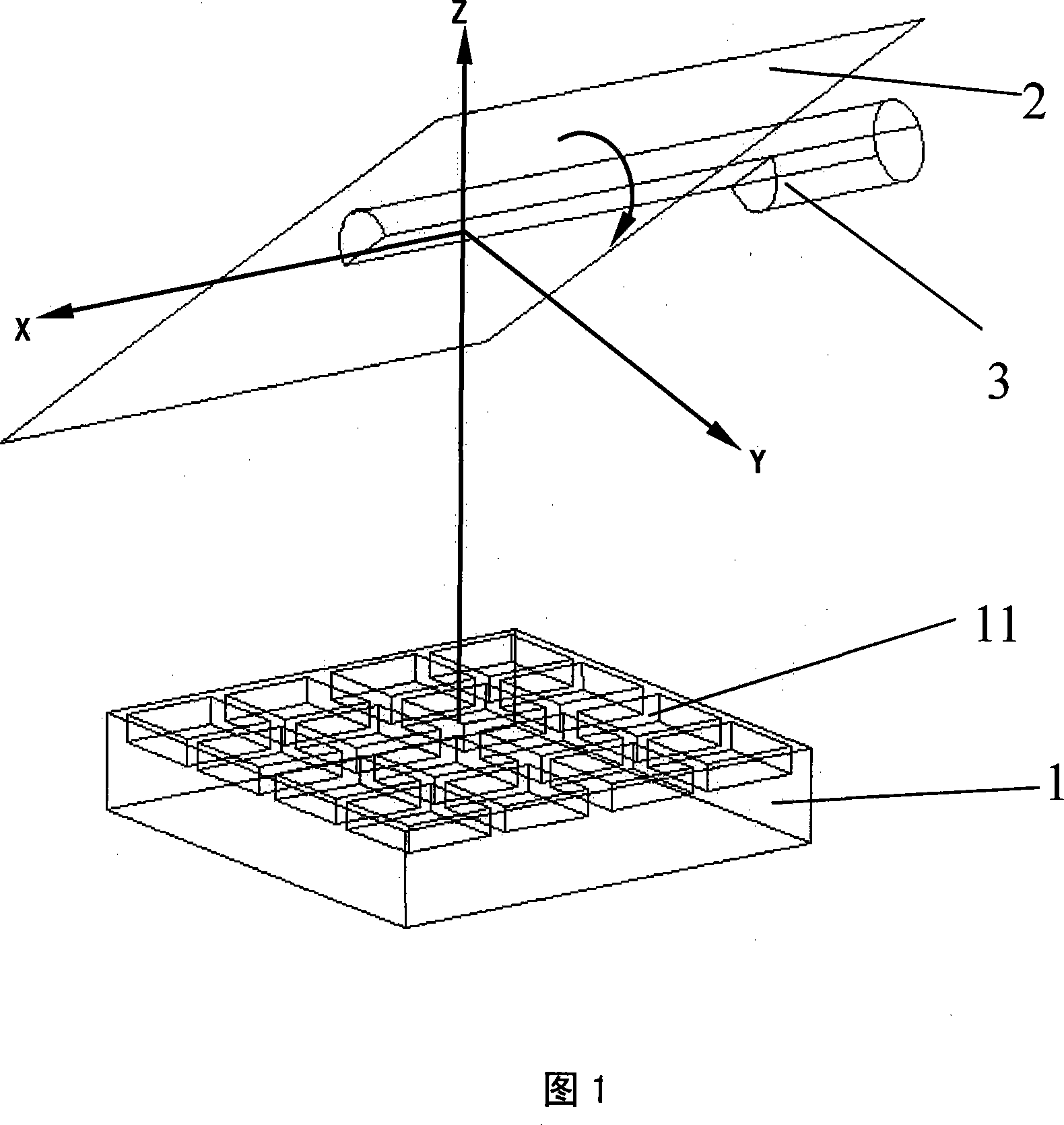
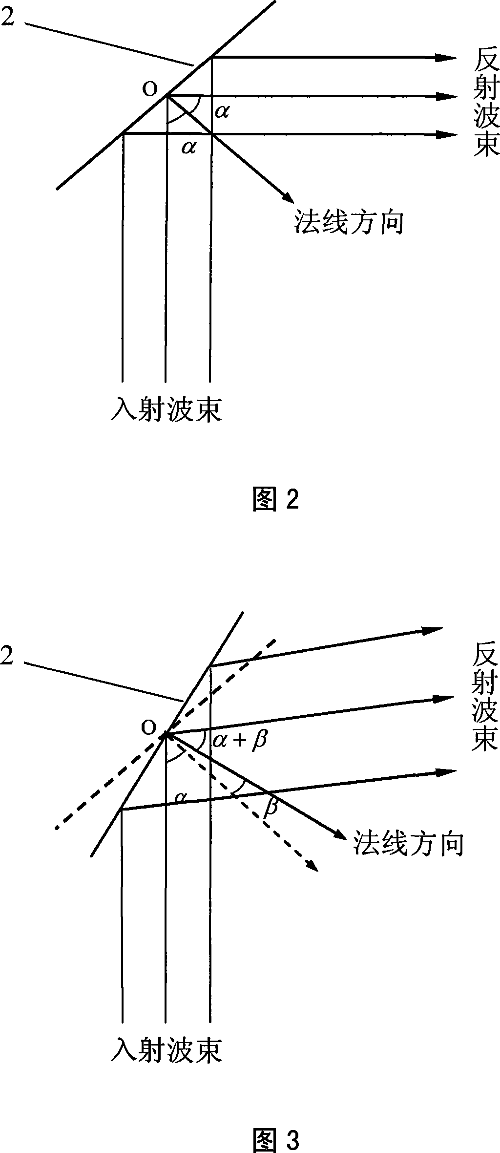
[0024] Referring to Fig. 1 to Fig. 3, the present invention adopts array antenna feeding, and realizes beam scanning technology by rotating the antenna reflecting surface, including steps:
[0025] ①The array antenna 1 is designed according to the working frequency, and the array antenna 1 is designed with M×N array units 11 according to the requirements of the antenna gain. M or N is a natural number greater than 1, and the array antenna 1 is installed on the On the antenna platform, the radiation beam is directed to the reflecting mirror 2 . The array structure of the array antenna 1 of the present invention is a rectangular array, or a circular array, or a tapered distribution array, or a rectangular array with unequal spacing, or a tapered distribution array with unequal spacing. The units of the array unit 11 of the present invention are configured as microstrip antennas, or antennas in the form of waveguide, or slot antennas, or horn antennas, or antennas in the form of ...
PUM
 Abstract
Description
Claims
Application Information