Automatic recognition method and encryption method of pluggable optical module

A technology of automatic identification and encryption method, which is applied in the field of communication and can solve the problem that the reliability of the module cannot be guaranteed.

Inactive Publication Date: 2008-03-05
ZTE CORP
View PDF0 Cites 21 Cited by
  • Summary
  • Abstract
  • Description
  • Claims
  • Application Information

AI Technical Summary

Problems solved by technology

[0006] With the development of technology, pluggable optical modules are widely used, which leads to the following problems: Since there are many manufacturers of pluggable optical modules, many optical modules can be purchased directly from the market. In terms of interfaces, it may be possible to achieve full compatibility, but the reliability of these modules cannot be guaranteed; in additi

Method used


Image

  • Automatic recognition method and encryption method of pluggable optical module
  • Automatic recognition method and encryption method of pluggable optical module
  • Automatic recognition method and encryption method of pluggable optical module

Examples


Embodiment Construction

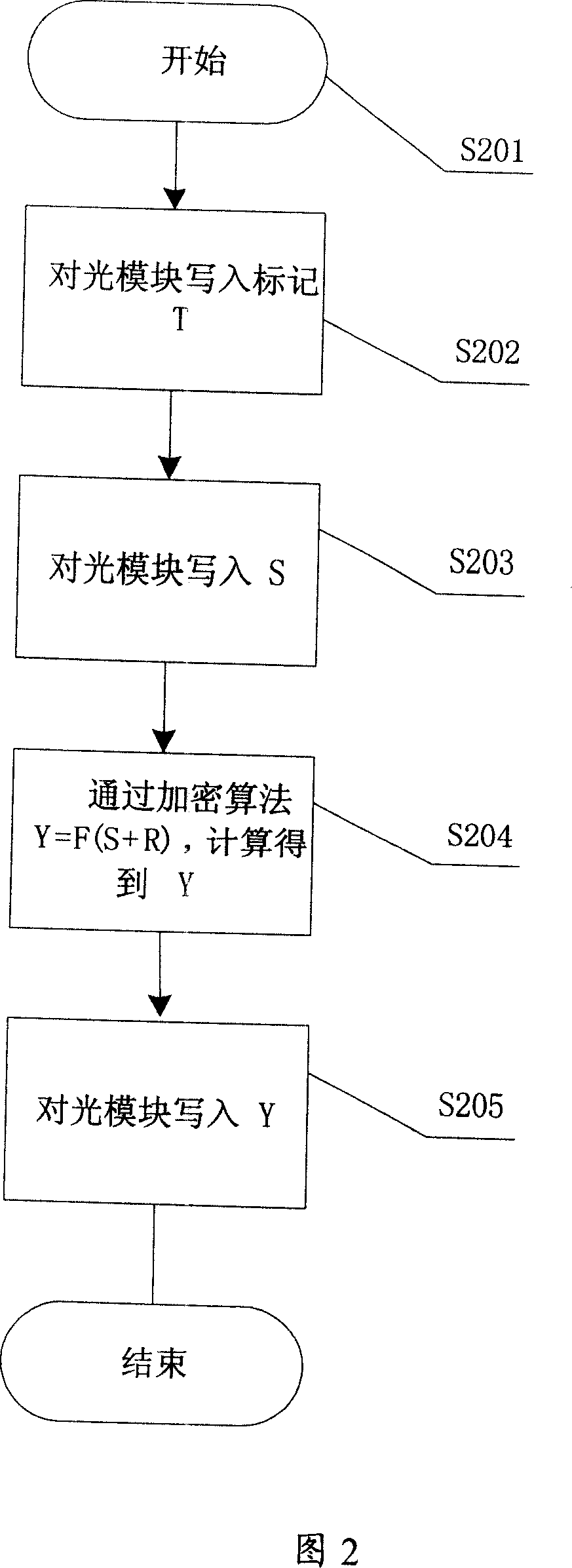
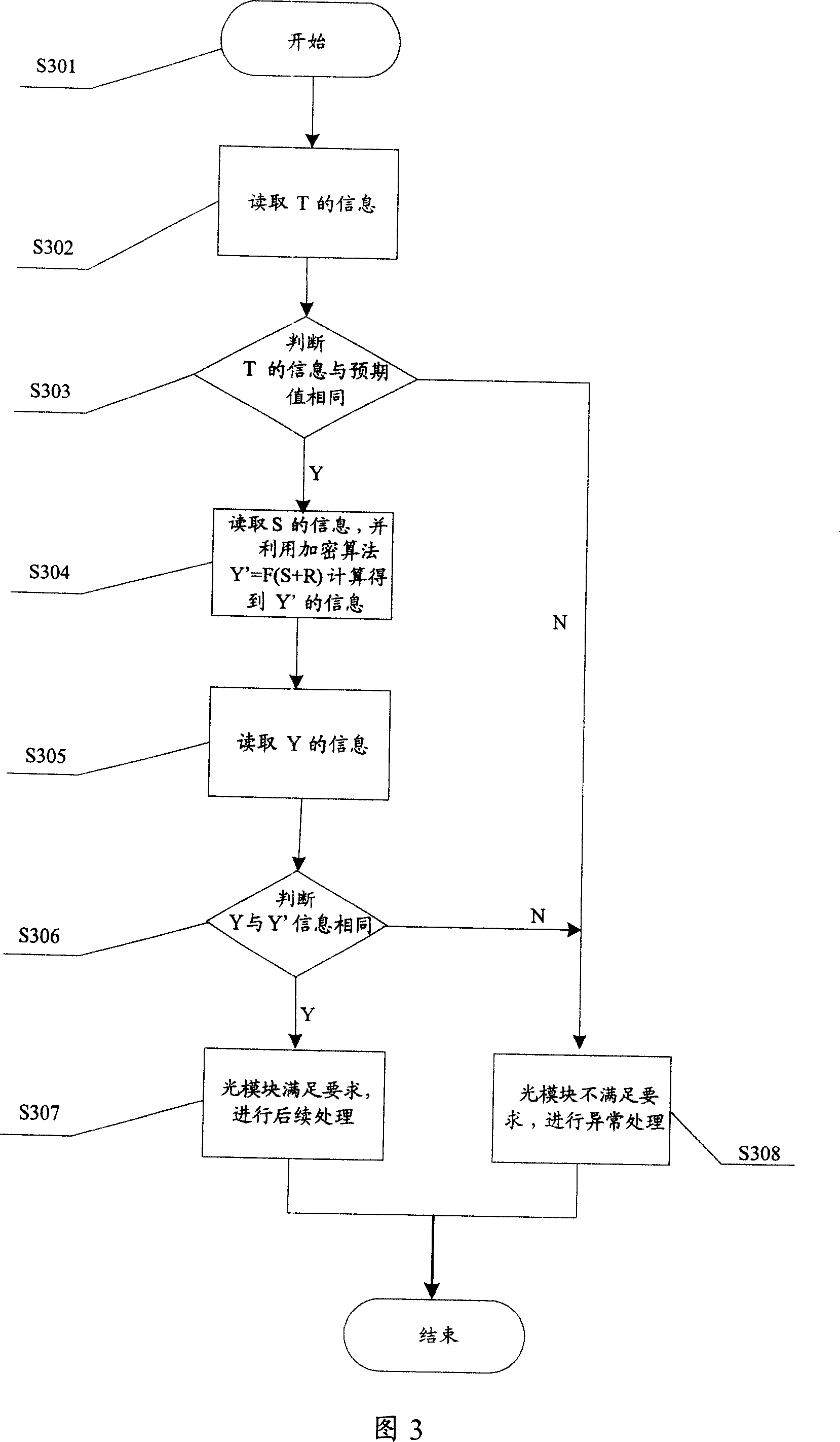
[0034] According to the relevant standards of pluggable optical modules, most pluggable optical modules reserve some registers for read and write operations. This solution is to use these registers to automatically identify the optical module, and it is also a prerequisite for the realization of this solution to use these registers for read and write operations.

[0035] Preferred embodiments of the present invention will be described in detail below with reference to the accompanying drawings.

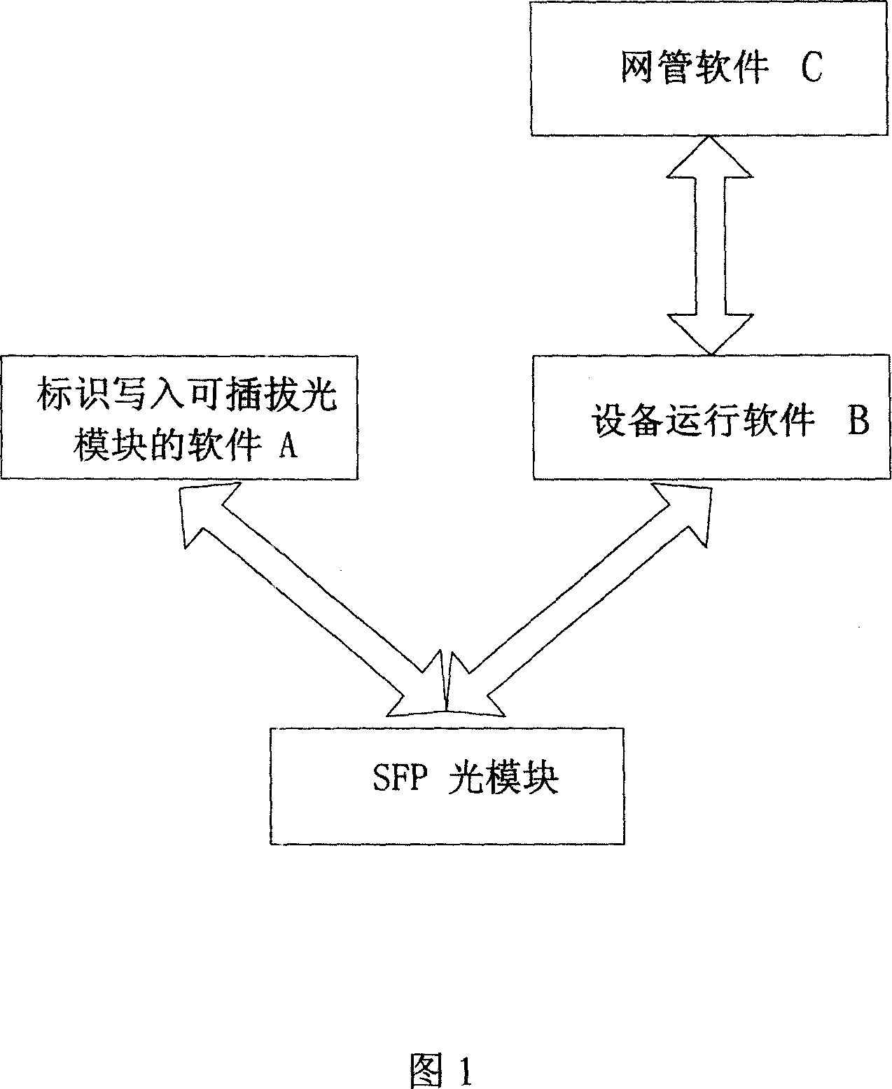
[0036] As shown in Figure 1, the hardware part involved in the present invention includes:

[0037] (1) One PC, which is used to install the software for writing the logo into the pluggable optical module and the network management software.

[0038] (2) The equipment used to write into the pluggable optical module is referred to as sintering equipment hereinafter for the convenience of description.

[0039] (3) The actual operating equipment, that is, the equipment used in the actu...


PUM


Abstract

This invention discloses a method for discriminating pluggable optical modules including the following steps: plugging an optical module with written check information into a device using said module, which reads the label of the module to compare the label with its expected value, if they are the same, then the optical module is checked continuously, the device reads the content of the optical module serial number and inputs it with character strings kept in the program to be computed with a ciphered algorithm to output a second ciphered message, the device reads a first ciphered message and compares it with the second, if they are different, it shows that the module does not meet the requirement and processes it abnormally, if they are the same, the module meets the requirement. This invention also discloses a ciphering method.

Description

technical field [0001] The invention relates to a communication technology, in particular to an automatic identification method and an encryption method of a pluggable optical module. Background technique [0002] In communication equipment, a large number of optical fibers are used for data transmission media, and the use of optical modules is naturally indispensable. In the early equipment, the optical module was directly soldered to the single board. If the optical module fails, the entire single board needs to be replaced. With the development of technology, a large number of pluggable optical modules are used in the current communication equipment, and corresponding optical module slots are reserved on the equipment. In actual use, the optical module only needs to be inserted into the slot to use. [0003] Such processing has two advantages: [0004] (1) If only the optical module has a problem, just replace the optical module without replacing the entire board. [0...

Claims


Application Information

Patent Timeline
IPC IPC(8): H04B10/02H04B10/25H04B10/85
Inventor 张萌罗亚军许力鑫
Owner ZTE CORP
Why Eureka
Try Eureka