Network clock synchronous method, device and system

A clock synchronization and network clock technology, applied in the direction of synchronization device, transmission system, network interconnection, etc., can solve the problem that the clock cannot be synchronized, and achieve the effect of small clock deviation

Inactive Publication Date: 2008-03-05
SUPCON GRP +1
View PDF0 Cites 15 Cited by
  • Summary
  • Abstract
  • Description
  • Claims
  • Application Information

AI Technical Summary

Problems solved by technology

[0005] The problem to be solved by the embodiments of the present invention is to provide a network clock synchronization method, devic

Method used


Image

  • Network clock synchronous method, device and system
  • Network clock synchronous method, device and system
  • Network clock synchronous method, device and system

Examples


Embodiment Construction

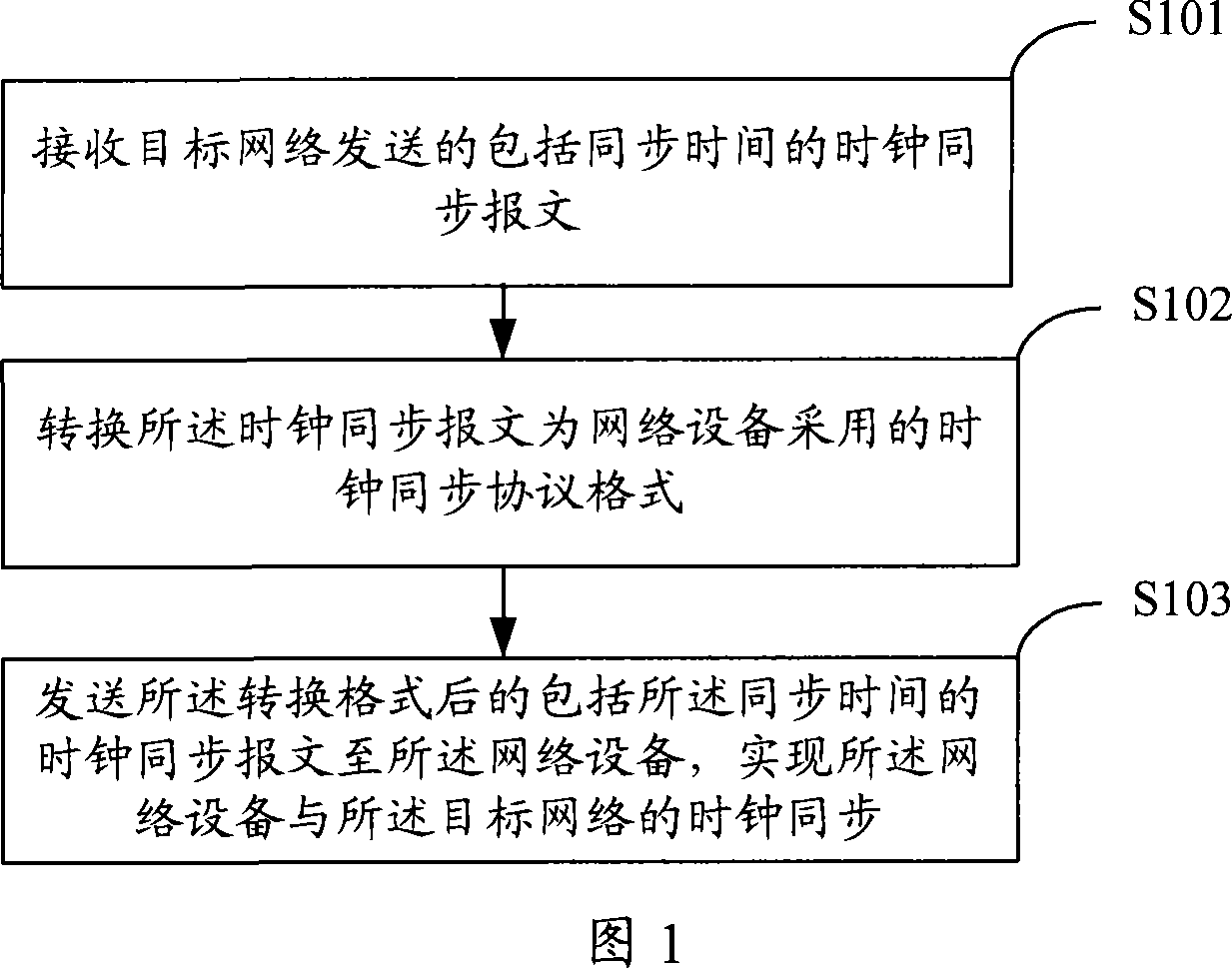
[0068] The present invention will be described in detail below in conjunction with the accompanying drawings and embodiments. Please refer to the flow chart of the network clock synchronization method provided by the present invention shown in Figure 1, which specifically includes steps:

[0069] Step S101: receiving a clock synchronization message including synchronization time sent by the target network;

[0070] Step S102: converting the clock synchronization message into a clock synchronization protocol format adopted by the network device;

[0071] Step S103: Send the clock synchronization message including the synchronization time after the converted format to the network device, so as to realize clock synchronization between the network device and the target network.

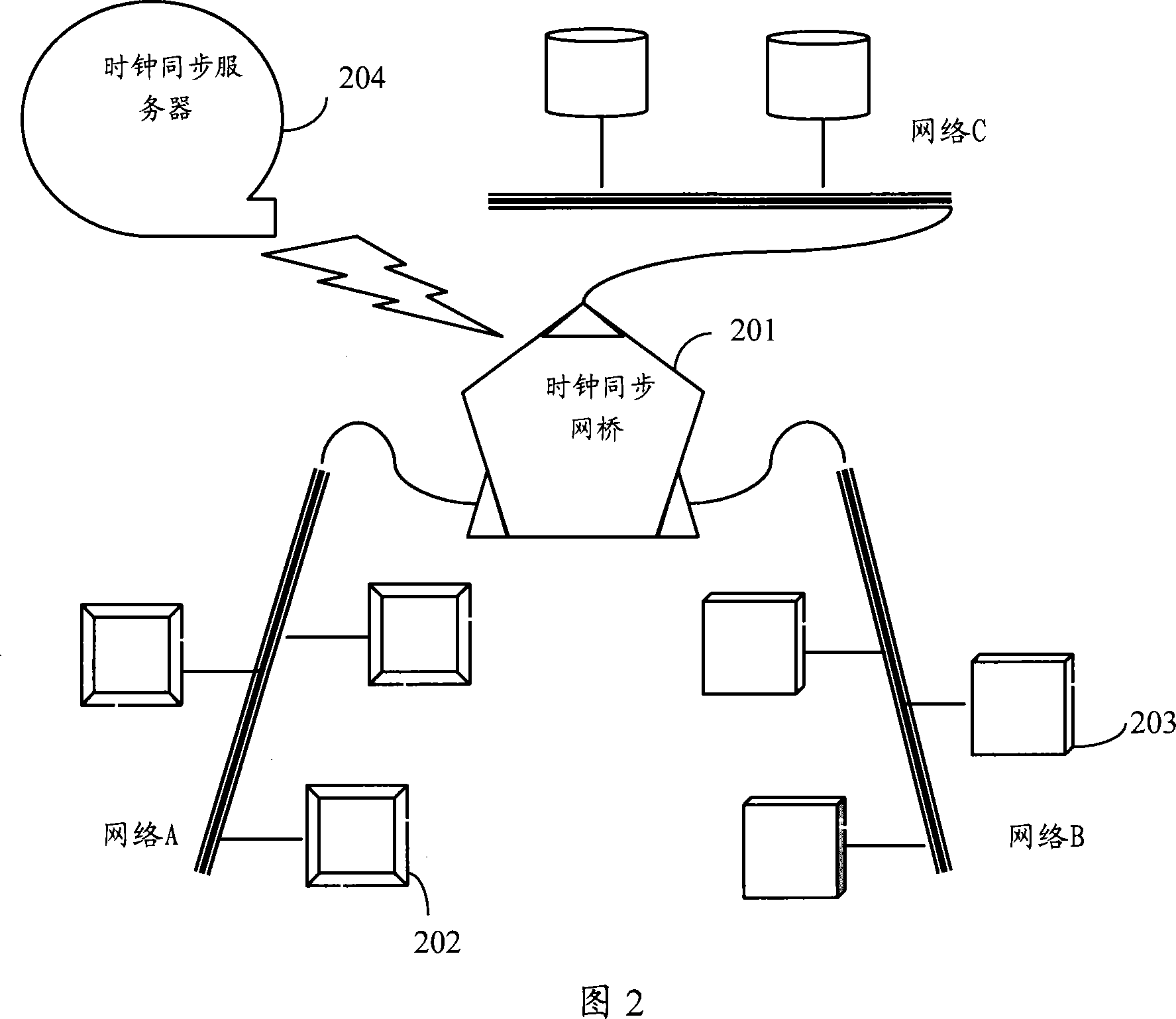
[0072] In a preferred embodiment of the present invention, please refer to Fig. 2 for the topological structure diagram of the network, and the clock synchronization bridge 201 is respectively connected ...


PUM


Abstract

The method includes steps: receiving clock synchronization (CS) message including synchronizing time (CT) sent from the objective network; converting CS message to format of CS protocol adopted by network device; sending the format converted CS message including CT to network device to implement CS between the network device and the objective network. The method can realize CS among networks when interconnected networks use different CS protocols. Correspondingly, the invention also discloses devices and system for CS of network.

Description

technical field [0001] The invention relates to the field of industrial control, in particular to a network clock synchronization method, device and system. Background technique [0002] With the development and maturity of Ethernet technology, Ethernet technology is more and more applied in industrial occasions. The running time of the equipment on the industrial Ethernet must be synchronized to ensure the normal operation of the industrial occasion. Due to the high real-time requirements of industrial Ethernet, there are many clock synchronization protocols specially applied to industrial Ethernet. These protocols can meet the high real-time requirements of industrial Ethernet, but they may not be compatible with clock synchronization protocols of other common networks such as office automation networks. For example, industrial Ethernet generally uses Precision Time Protocol (PTP) with very high clock accuracy, while ordinary office automation networks often use Network ...

Claims


Application Information

Patent Timeline
IPC IPC(8): H04L7/00H04L12/46H04L12/56H04L29/06
Inventor 冯冬芹章涵金建祥褚健
Owner SUPCON GRP
Why Eureka
Try Eureka