Real-time clock synchronization circuit of battery management system and method thereof

A battery management system, real-time clock technology, applied in logic circuits, electrical components, pulse technology, etc., can solve problems such as hidden quality problems, abnormal clock chip operation, and difficulty in battery life to meet product life requirements, to simplify inconvenience and achieve Redundant design, the effect of enhancing reliability

Active Publication Date: 2015-03-11
HUIZHOU EPOWER ELECTRONICS
View PDF5 Cites 6 Cited by
  • Summary
  • Abstract
  • Description
  • Claims
  • Application Information

AI Technical Summary

Problems solved by technology

[0005] (1) There is a bottleneck in the life of the small battery that powers the clock chip. In applications like industrial or new energy vehicles, it is difficult for such batteries to meet the life requirements of the product
During the use of the product, due to the problem of the battery itself, it cannot provide stable power to the clock chip, causing the clock chip to work abnormally;
[0006] (2) If the battery management system is a part of automotive electronics, the quality level of electronic components is required to meet AECQ standards, and the current small battery products are not as good as traditional electronic components in terms of materials, operating temperature requirements and other conditions. It is suitable to be used alone as an internal device of an electronically controlled power supply, and there are quality risks;
[0007] (3) When the clock chip itself fails, because there is no reference object, it is impossible to accurately judge whether the clock chip is working abnormally
Such failures have adverse effects on the later user experience and system optimization design

Method used


Image

  • Real-time clock synchronization circuit of battery management system and method thereof
  • Real-time clock synchronization circuit of battery management system and method thereof
  • Real-time clock synchronization circuit of battery management system and method thereof

Examples


Embodiment Construction

[0045] The specific implementation manners of the embodiments of the present invention will be described in detail below in conjunction with the accompanying drawings.

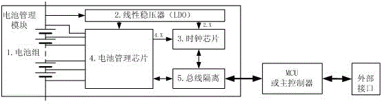
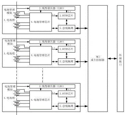
[0046] like figure 1 As shown, the block diagram of the real-time clock synchronization circuit of the general architecture of the battery management system of the present invention mainly includes a battery management module, a main controller module, and an external communication interface module. The battery management module, the main controller module, and the external communication interface module are connected in sequence. figure 2 It is a block diagram of the real-time clock synchronization circuit of the distributed architecture battery management system of the present invention. The "distributed" mainly refers to the use of multiple battery management modules distributed and connected to the main controller. The advantage of using a distributed architecture is that it can realize Redundancy of the ...


PUM


Abstract

The invention discloses a real-time clock synchronization circuit of a battery management system and a method thereof. The real-time clock synchronization circuit comprises a battery management module, a main controller module and an external communication interface module, wherein the battery management module, the main controller module and the external communication interface module are connected in sequence through buses; the battery management module is used for carrying out unified control and management on multiple strings of batteries in a battery pack; the main controller module is used for controlling and managing an integral clock monitoring circuit; and the external communication interface module is used for providing an information interaction channel for carrying out time synchronization with external equipment. According to the real-time clock synchronization circuit of the battery management system, which is provided by the invention, additional arrangement of an onboard battery for power supply of a clock chip is not needed and the clock chip is arranged in a distributed manner, so that the accuracy for timing of the clock chip and the clock self-synchronizing alignment function are improved.

Description

technical field [0001] The invention relates to the field of battery management systems, in particular to a real-time clock monitoring circuit and method for the battery management system. Background technique [0002] At this stage, the power battery or energy storage battery system is generally equipped with a battery management system, and in general, the battery system requires the battery management system to have the function of recording the historical faults of the battery system, and accurately record the time when the historical fault data occurs. [0003] At present, the battery management system adopts a solution similar to other traditional electronic control equipment, and uses a combination of a small battery and a clock chip circuit to realize a real-time clock circuit. Among them, the clock chip has many IC-level solutions, and the supporting small battery uses To provide power supply for the clock chip when the battery management system is not working, to e...

Claims


Application Information

Patent Timeline
Patent Type & Authority Applications(China)
IPC IPC(8): H03K19/00
Inventor 刘飞文锋阮旭松王占国盛大双
Owner HUIZHOU EPOWER ELECTRONICS
Why Eureka
Try Eureka