Blade for vertical shaft windmill and lift type vertical shaft windmill having the same

A vertical axis and blade technology, applied in the field of vertical axis windmill blades and lift type vertical axis windmills equipped with such blades, can solve the problems of the limit of friction surface durability, lack of specificity, and impracticality, etc., and achieve simple Structure, the effect of suppressing excessive rise

Inactive Publication Date: 2008-03-05
INTPROP BANK CORP (JP)
View PDF1 Cites 11 Cited by
  • Summary
  • Abstract
  • Description
  • Claims
  • Application Information

AI Technical Summary

Problems solved by technology

[0007] However, in the structure of the spoiler shown in FIG. 7 and FIG. 8 of the above-mentioned publication (Patent Document 1), what kind of structure is installed on the blade with very limited space, and what kind of operating parameters can open or close the control plate? Closed, totally non-specific, non-realizable
[0008] Also, for strong winds up to a certain level, there is a method of installing an electromagnetic brake on the output shaft of the wind turbine to slow it down so that it can continue to operate, but in this case, it is always necessary to operate it. Electricity, or need to generate current The receiving load, on the other hand, has the disadvantages of continuous action on the output shaft, excessive torque, etc.
In addition, as another method, a method of decelerating it with a mechanical brake is also conceivable, but there are difficult problems such as the removal of heat generated by the friction disc and the limit of the durability of the friction surface, and there is no practically effective solution.

Method used


Image

  • Blade for vertical shaft windmill and lift type vertical shaft windmill having the same
  • Blade for vertical shaft windmill and lift type vertical shaft windmill having the same
  • Blade for vertical shaft windmill and lift type vertical shaft windmill having the same

Examples


Embodiment Construction

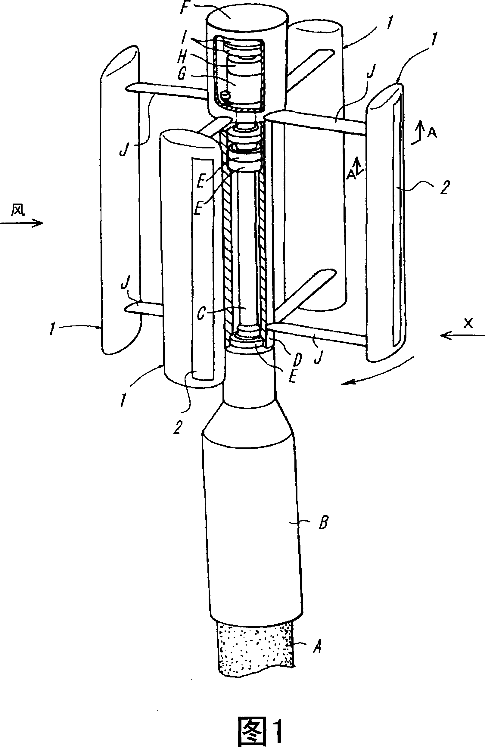
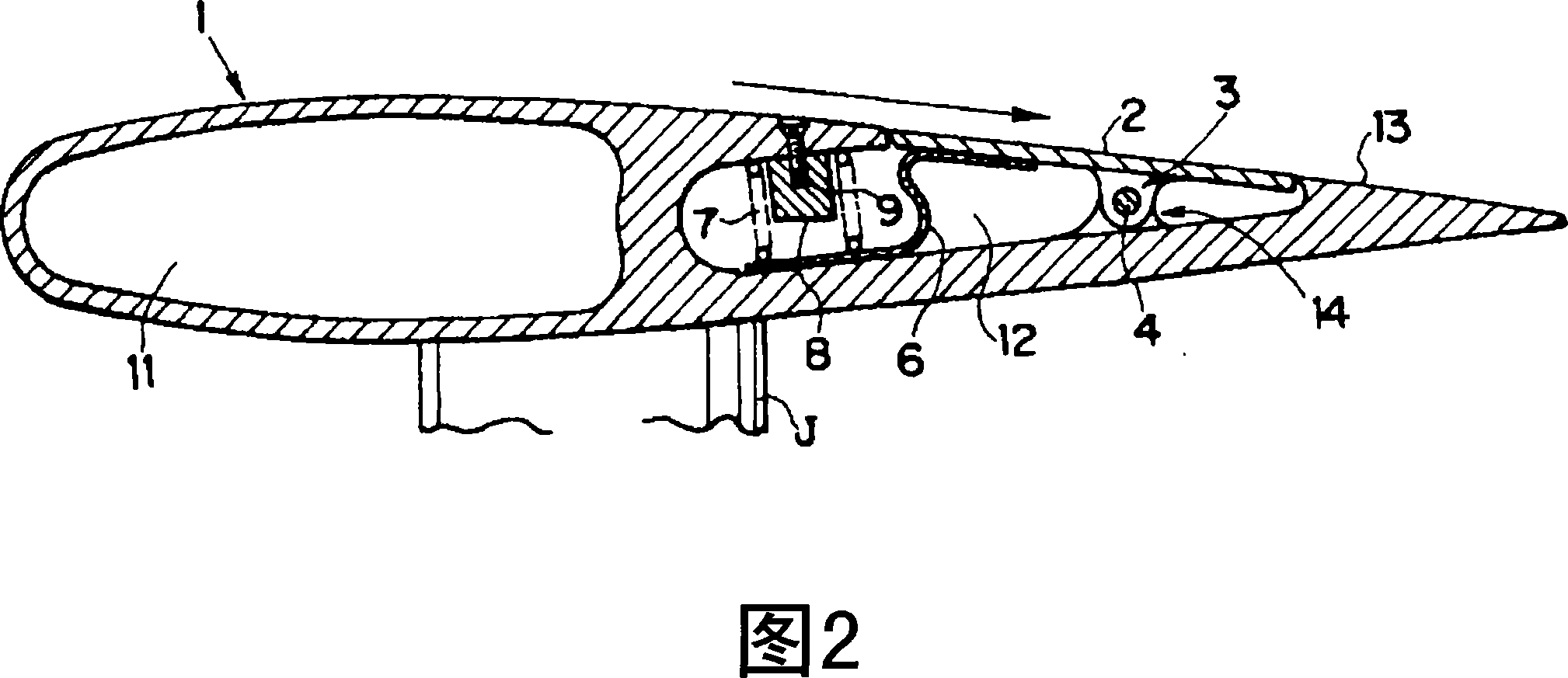
[0037] The best mode for implementing the blade for a vertical axis windmill of the present invention will be described with reference to the drawings. Fig. 1 is a partially cutaway perspective view of a straight airfoil type vertical axis wind turbine using blades for a vertical axis wind turbine according to the present invention. Fig. 2 is an A-A cross-sectional view of the best mode for carrying out the blade for a vertical axis windmill of the present invention.

[0038] As shown in Fig. 1, the linear airfoil type vertical axis windmill has a cylindrical mounting part B mounted on a column-shaped installation platform A such as a utility pole, and a cylindrical mounting part B fixed to the mounting part B and arranged vertically on the axis. A round bar-shaped fixed shaft C, a bearing E mounted on the outer circumference of the fixed shaft C, a cylindrical outer ring sleeve D mounted on the outer circumference of the bearing E and capable of rotating around the fixed shaf...


PUM


Abstract

The present invention provides a blade for a vertical shaft windmill capable of easily suppressing the excessive rise of the rotating speed of the windmill by a simple mechanical structure when the rotating speed rises beyond a prescribed value when wind is blowing at a high velocity and a lift type vertical shaft windmill having the blade. This blade (1) comprises an air brake (2) and a bearing (3) mounted on the trailing edge side thereof from the gravity center of the air brake (2). The air brake (2) is rotatably mounted in the blade (1) through the bearing (3). Also, a spring receiving plate (6) of roughly S-shape is mounted on the front inner surface of the air brake (2). The spring receiving plate (6) is largely projected forward of the air brake (2) and energized by a spring material (7) stored at the front part of a wind receiving chamber (12). When the rotating speed of the windmill rises beyond the prescribed value, the leading edge side of the air brake (2) is projected from the surface of a wing by a centrifugal force, and the trailing edge side of the air brake (2) is sunk from the surface of the wing. Accordingly, since an air resistance producing part is formed, the rise of the rotating speed of the windmill can be suppressed.

Description

technical field [0001] The present invention relates to a blade for a vertical axis windmill, which is provided with a support arm on the rotation shaft of a vertical axis windmill, receives headwind to generate a lift force, and rotates the rotation shaft by the lift force, and a lift type vertical axis windmill equipped with the blade, as a windmill Specific forms of the present invention relate to straight-winged Darrieus type windmills, eggbeater type windmills, and vertical axis windmills having elements thereof. Background technique [0002] As windmills capable of converting wind energy into power with relatively high energy conversion efficiency, conventionally known are horizontal-axis propeller-type windmills, egg-beater-type windmills having a vertical rotation axis, and straight-wing egg-beater-type windmills. Among them, the horizontal-axis propeller type windmill is adopted for most of the large-scale windmills in recent years. For the egg-beating windmill, it...

Claims


Application Information

Patent Timeline
Patent Type & Authority Applications(China)
IPC IPC(8): F03D7/06F03D3/06
CPCF03D3/005F05B2240/31F03D7/06F03D7/0252F05B2240/214F03D3/061Y02E10/74
Inventor 横井正
Owner INTPROP BANK CORP (JP)
Why Eureka
Try Eureka