Electromechanical switching device

A technology of switchgear, electromechanical switch, applied in the direction of electric switch, substation/switch layout details, protection switch terminal/connection, etc., which can solve problems such as wiring errors

Inactive Publication Date: 2008-03-05
SIEMENS AG
View PDF0 Cites 7 Cited by
  • Summary
  • Abstract
  • Description
  • Claims
  • Application Information

AI Technical Summary

Problems solved by technology

In this case, there is a risk of wiring errors when reconnecting the switchgear to the wiring

Method used


Image

  • Electromechanical switching device
  • Electromechanical switching device
  • Electromechanical switching device

Examples


Embodiment Construction

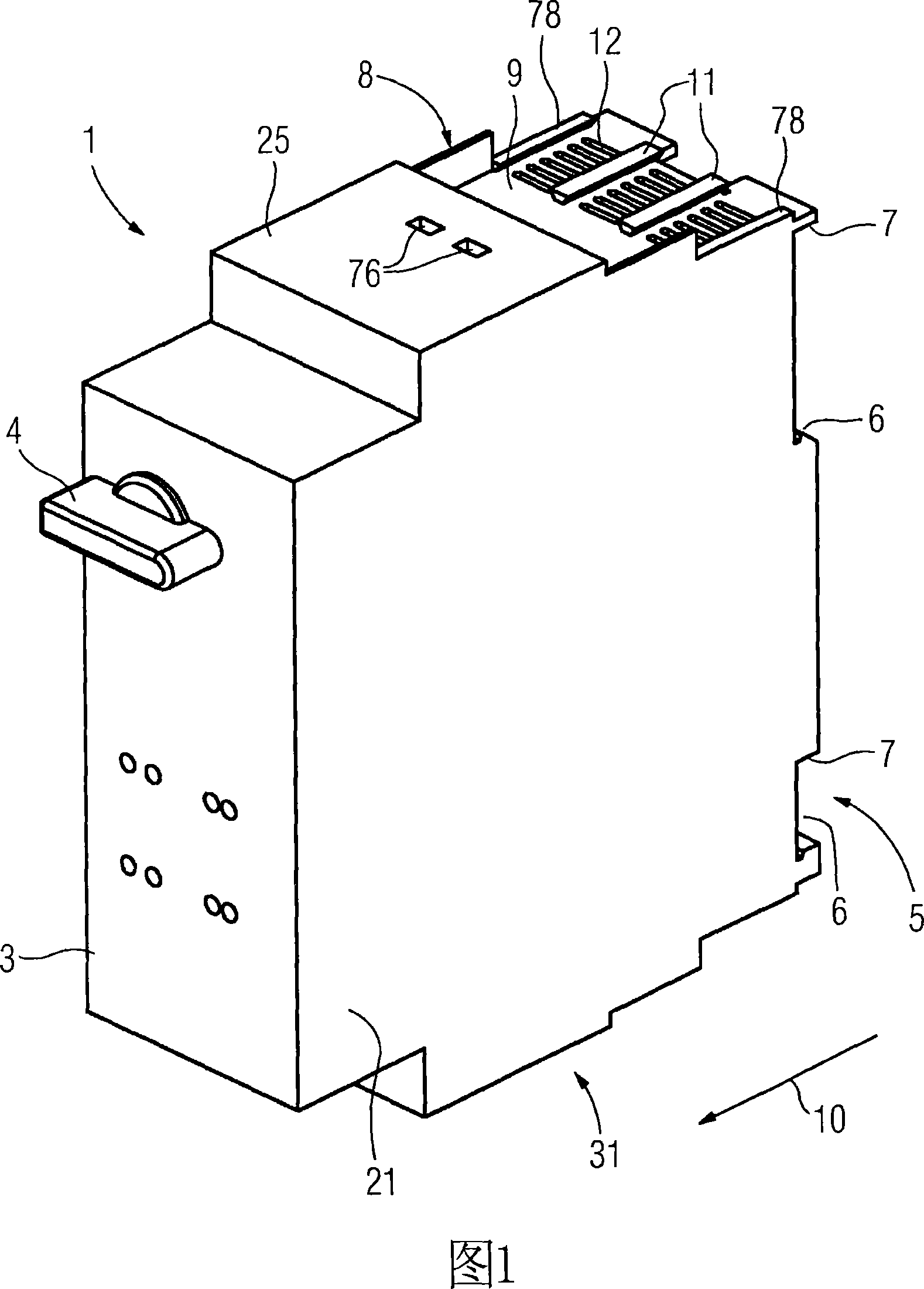
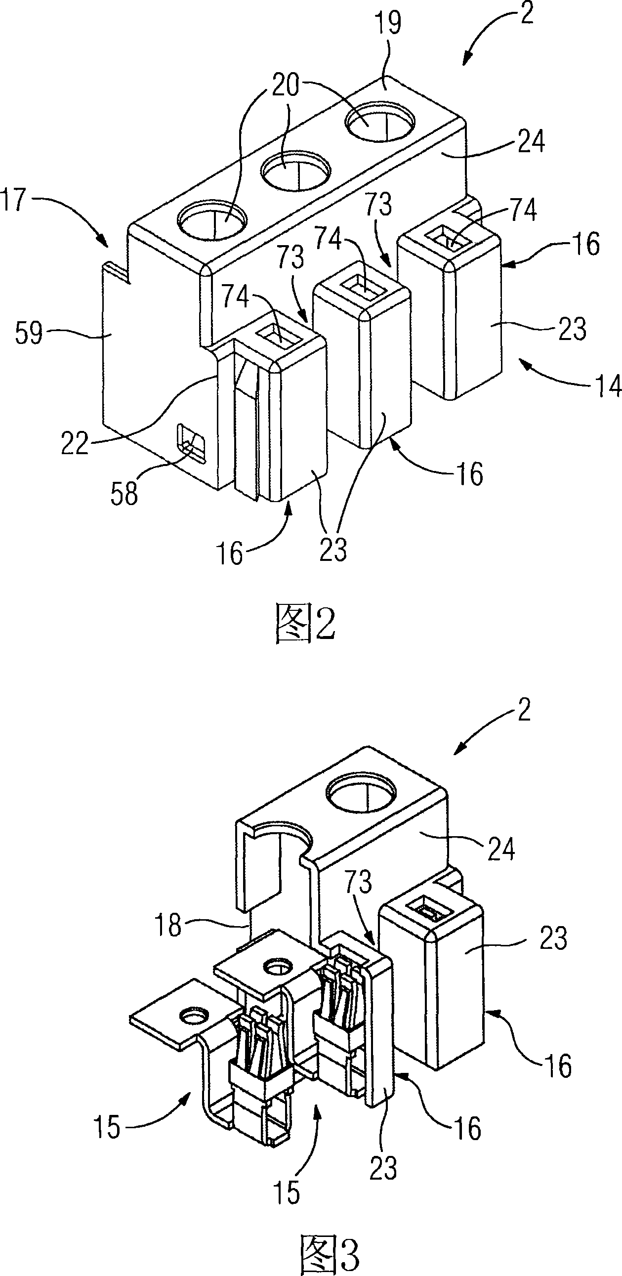
[0024] In the simplest case, the switching device according to the invention comprises a switching device body 1 (see FIG. 1 ) and a connection module 2 (see FIGS. 2 and 3 ). The switching device body 1 has on its front side 3 a rotary switch 4 for operating the switching device. The back side 5 of the switchgear body 1 is provided with a fastening protrusion in the form of two fastening grooves 6 across the entire backside and two ribs 7, which are used to connect the switchgear body 1 with other assembly components (see Figure 8 or Figure 10). On the upper surface 8 of the switchgear main body 1, there is an embedded installation surface 9 adopting a sunken arrangement, on which guide strips 11 with a trapezoidal cross-section extending along the longitudinal direction 10 of the casing are installed, and these guide strips are used In the establishment of dovetail joints (dovetail connections). Between the guide strips 11 there are a large number of ventilation holes 12 le...


PUM


Abstract

The invention relates to an electromechanical switchgear, a switchgear arrangement and an electrical connection module. In order to simplify the connection of an electromechanical switchgear, the invention provides a switchgear with a switchgear body (1) and a connection module (2) connectable to the switchgear body (1), the connection module having At least one connection terminal (15) for the main circuit of the switchgear. A basic idea of ​​the invention is to replace the hitherto monolithic construction of switchgears with a modular construction. Therein, a certain number of connection terminals (15) for each switchgear are collected in one or more connection modules (2) connectable to the switchgear main body (1). That is to say, the connection module (2) can be installed separately without being installed together with the switchgear main body (1). This makes it possible to prewire the terminals ( 15 ) without actually installing the actual switching device. The installation of the switchgear main body (1) must be carried out later.

Description

technical field [0001] The invention relates to an electromechanical switchgear, a switchgear arrangement and an electrical connection module. Background technique [0002] In electromechanical switching devices such as motor protective switches, contactors, overload relays and other types of devices for switching, protecting and starting electric motors and systems, the terminals for the main circuit are usually permanently integrated in the switchgear. Therefore, the wires connected to the respective terminals must be removed from the switchgear when replacing the switchgear. In this case, there is a risk of wiring errors when reconnecting the switchgear to the wiring. Contents of the invention [0003] It is therefore an object of the invention to simplify the connection of electromechanical switching devices. This object is achieved by an electromechanical switching device according to claim 1 , a switching device arrangement according to claim 9 and an electrical co...

Claims


Application Information

Patent Timeline
Patent Type & Authority Applications(China)
IPC IPC(8): H01H71/08H02B1/056H01R9/24
CPCH01R9/2408H01R9/2491H01H71/08H01H11/0031H01H2011/0037
Inventor 罗伯特·阿邓卡伯索尔德·赫尔德曼
Owner SIEMENS AG
Why Eureka
Try Eureka