Solar vehicular air conditioner control system

A technology for control systems and solar vehicles, applied in heating and ventilation control systems, heating and ventilation safety systems, applications, etc., can solve problems such as space occupation and easy blocking

Inactive Publication Date: 2008-03-12
CPUMATE INC
View PDF0 Cites 6 Cited by
  • Summary
  • Abstract
  • Description
  • Claims
  • Application Information

AI Technical Summary

Problems solved by technology

However, the additional air-conditioning system makes the driver not only spend a considerable amount of money, but also in the case of limited space in the car, installing an additional

Method used


Image

  • Solar vehicular air conditioner control system

Examples


Embodiment Construction

[0023] Relevant technical content and detailed description of the present invention, now cooperate accompanying drawing to explain as follows:

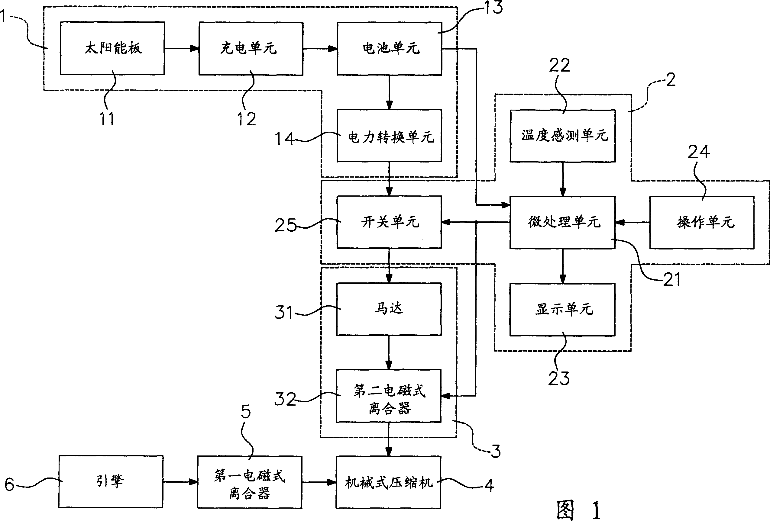
[0024] FIG. 1 is a schematic circuit block diagram of a solar vehicle air-conditioning control system of the present invention. As shown in Figure 1 : the solar vehicle air-conditioning control system of the present invention includes: a solar power supply device 1 , a control device 2 and a power device 3 . When the vehicle engine stops running, the driver controls the solar power supply device by starting the control device, and starts the vehicle air-conditioning system with solar power supply to generate cold air and input it into the car. The vehicle is exposed to sunlight for a long time, making the car The temperature is kept within the range that can be adapted to the person.

[0025] The solar power supply device 1 includes: a solar panel 11 , a charging unit 12 , a battery unit 13 and a power conversion unit 14 . The charg...


PUM


Abstract

The invention relates to a vehicular solar air conditioning control system which comprises a solar power supply device, a control device and a power device. When a vehicular engine stops running, a driver presses a key of the control device to start the control device; the output signal and the power supply outputted by the solar power supply device drive the power device to start, which results in that the power device drives the operation of a mechanical compressor of the vehicular air conditioning system and the cold air produced by the vehicular air conditioning system is inputted into a vehicle in order to make the vehicular temperature kept in a temperature range which the people can adapt to.

Description

technical field [0001] The invention relates to a solar air-conditioning control system, in particular to a vehicle air-conditioning system started by solar power supply. Background technique [0002] Since most of the current parking lots are open-air designs, when the vehicle is parked in the open-air parking lot, the temperature inside the car is likely to rise due to sunlight. When the driver returns to the car, the high temperature generated in the car is usually Between 50 and 80°C. The high temperature is generated because the windows are all opened and closed, the inside of the car cannot convect with the outside air, so the driver will open all the doors and start the engine, and then start the car air conditioning system to run, so that the high temperature inside the car can be compared with the outside air. Convection of the air to reduce the temperature inside the car. Although this method can gradually reduce the temperature inside the car, it takes a while t...

Claims


Application Information

Patent Timeline
IPC IPC(8): F24F11/00F04B35/00B60H1/32
Inventor 林国仁曾添志叶海瑞刘文荣
Owner CPUMATE INC
Why Eureka
Try Eureka