Method and system for dynamic laying-out interface element

A technology of interface elements and dynamic layout, applied in the direction of program control devices, etc., can solve problems such as affecting the processing speed of web pages, difficult to achieve dynamic effects, and insufficient freedom

Inactive Publication Date: 2008-03-12
KINGDEE SOFTWARE(CHINA) CO LTD
View PDF0 Cites 44 Cited by
  • Summary
  • Abstract
  • Description
  • Claims
  • Application Information

AI Technical Summary

Problems solved by technology

[0011] For example, the absolute positioning methods of Scheme 1 and Scheme 2 have the advantages of conforming to habits and being easy to use; however, absolute positioning cannot be dynamically changed at runtime
When the display size of the interface where the control is located changes (for example, due to the adjustment of the resolution), the layout position of the control in the interface should change dynamically, but the above schemes 1 and 2 using the absolute positioning method Cannot change dynamically, it is difficult to achieve dynamic effects
[0012] For scheme 3, although the dynamic adjustment of the position of the control can be realized, it is more complicated to implement
For example, using the grid positioning method mainly divides the content of the web page into several areas, and then fills the corresponding content into different tables; processing speed (such as parsing and downloading)
In addition, the grid-like layout in the interface automation design tool is very inconvenient for users of IDE (Integrated Development Environment, computer program integrated development environment, such as eclipse, Visual Studio, Jbuilder, etc.). There is not enough freedom when dragging and placing controls (you need to construct a grid with certain rows and columns, and you need to accurately place the corresponding controls to the corresponding grid)
In addition, it is a boring and complicated work to figure out and set the numerous weights of rows, columns, and cells manually when the interface is complex, and it is very error-prone

Method used


Image

  • Method and system for dynamic laying-out interface element
  • Method and system for dynamic laying-out interface element
  • Method and system for dynamic laying-out interface element

Examples


Embodiment Construction

[0036]

[0037]

[0038]

[0039]

[0040]

[0041]

[0042]

[0043]

[0044]

[0045]

[0046]

[0047]

[0048]

[0049]

[0050]

[0051]

[0052]

[0053]

[0054]

[0055]

[0056]

[0057]

[0058]

[0059]

[0060]

[0061]

[0062]

[0063]

[0064]

[0065]

[0066]

[0067]

[0068]

[0069]

[0070]

[0071]

[0072]

[0073]

[0074]

[0075]

[0076]

[0077]

[0078]

[0079]

[0080]

[0081]

[0082]

[0083]

[0084]

[0085]

[0086]

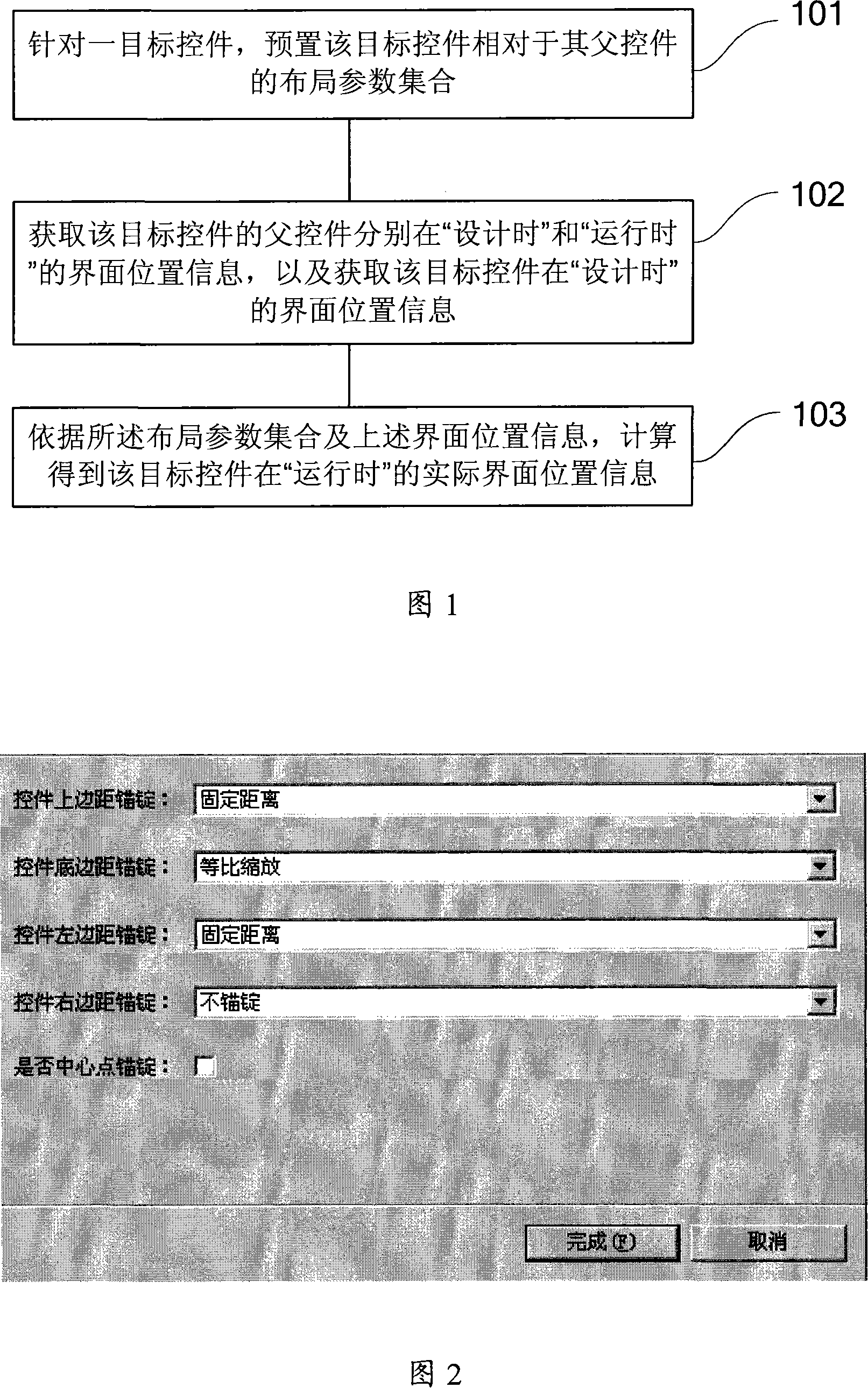
[0087] It is the element used to lay out the web interface through the grid. As the resolution of the display area is different, the size of the grid is also scaled according to the importance (that is, the weight) of a certain row or column of the grid, and a perfect grid can be achieved on the basis of accurately setting the weight Interface scaling performance. The various existing positioning methods mentioned above should be said to have their own strengths, and they can ...


PUM


Abstract

The present invention provides a method to realize dynamic interface element allocation comprising that as for a target control element, an allocation parameter set of a target control element is prearranged towards its parent control element. Wherein, the allocation parameter set is composed of a fixed distance mode and/or a uniform zoom mode, of which the fixed distance mode indicates each edge or a central point of the target control element is provided with a fixed distance towards a corresponding edge or a central point of the parent control element. In addition, the uniform zoom mode refers to that a distance between each edge of the target control element and a corresponding edge of the parent control element is uniformly zoomed according to actual situations. Interface position information of the parent control element for the target control element is obtained respectively during design and operation. Besides, the interface position information of the target control element is acquired. Based the said allocation parameter set and the interface position information, actual interface position information of the target control element during design and operation is obtained through calculation.

Description

technical field [0001] The invention relates to the technical field of man-machine interface, in particular to a method and system for dynamically arranging interface elements in a two-dimensional plane. Background technique [0002] In the human-machine interaction process (Human Machine Interaction), there is a level, which is what we call the interface. Human-machine interface GUI (Graphical User Interface, Graphical User Interface) is a communication environment needed for users to communicate with computers. [0003] In the two-dimensional plane of the usual man-machine interface, the layout of various interface elements is very important, and because all visual information (including background color) on the screen is drawn by the control. Therefore, by performing layouts for various controls, the layout of all elements on the screen can be realized. Among them, in order to determine the position of the controls in the interface, the following schemes are generally a...

Claims


Application Information

Patent Timeline
Patent Type & Authority Applications(China)
IPC IPC(8): G06F9/44
Inventor 宋大伟
Owner KINGDEE SOFTWARE(CHINA) CO LTD
Why Eureka
Try Eureka