Electric iron rack

A technology of electric soldering iron and iron frame, which is applied in the direction of soldering iron, electrical components assembly printed circuit, auxiliary device, etc., which can solve the problems of easily hurting people or other objects, time-consuming, and should not be scrubbed on wet sponges, etc.

Inactive Publication Date: 2008-03-19
HONG FU JIN PRECISION IND (SHENZHEN) CO LTD +1
View PDF0 Cites 7 Cited by
  • Summary
  • Abstract
  • Description
  • Claims
  • Application Information

AI Technical Summary

Problems solved by technology

Since the welding tip of the electric soldering iron is easy to be oxidized and damaged, it is necessary to add tin to the welding tip and melt it before doing the welding action, and then wipe it on a wet sponge to remove the oxide layer attached to the surface of the welding tip; to complete a certain part or After all the soldering operations, put the soldering iron back to the soldering iron stand. Because the temperature of the soldering tip is high, it is easy to hurt people or other objects, and the soldering iron cannot be placed at will. After the temperature of the soldering tip of the soldering iron drops, Add tin again to protect the soldering joint, and should not scrub it on a wet sponge, which is quite time-consuming, and the tools that must be used for existing soldering must be sorted out one by one when carrying, and the solder should be stored separately, or all tools can be directly stored Throw it in a large bag or box to carry, and the tools are placed quite disorderly

Method used


Image

  • Electric iron rack
  • Electric iron rack
  • Electric iron rack

Examples


Embodiment Construction

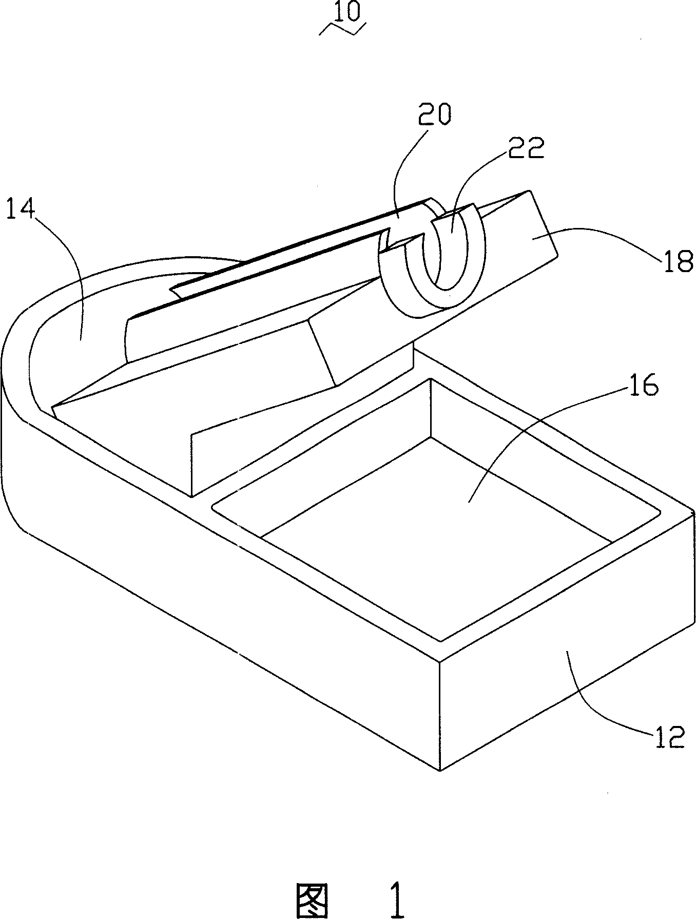
[0010] Please refer to Fig. 1 and Fig. 4, which is a preferred embodiment of the electric soldering iron stand 10 of the present invention, including a base 12, a support frame 18 is formed on the base 12, and a support frame 18 is formed on the base 12, and a The storage groove 14 and an accommodating groove 16 .

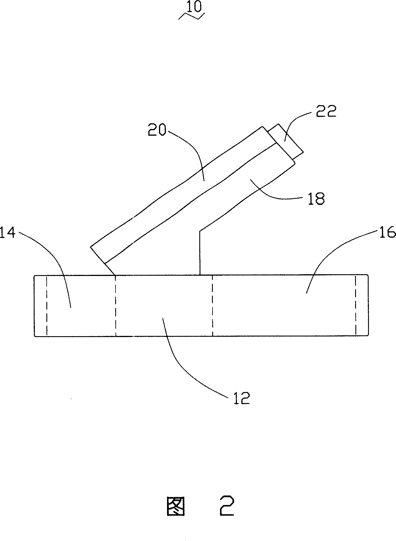
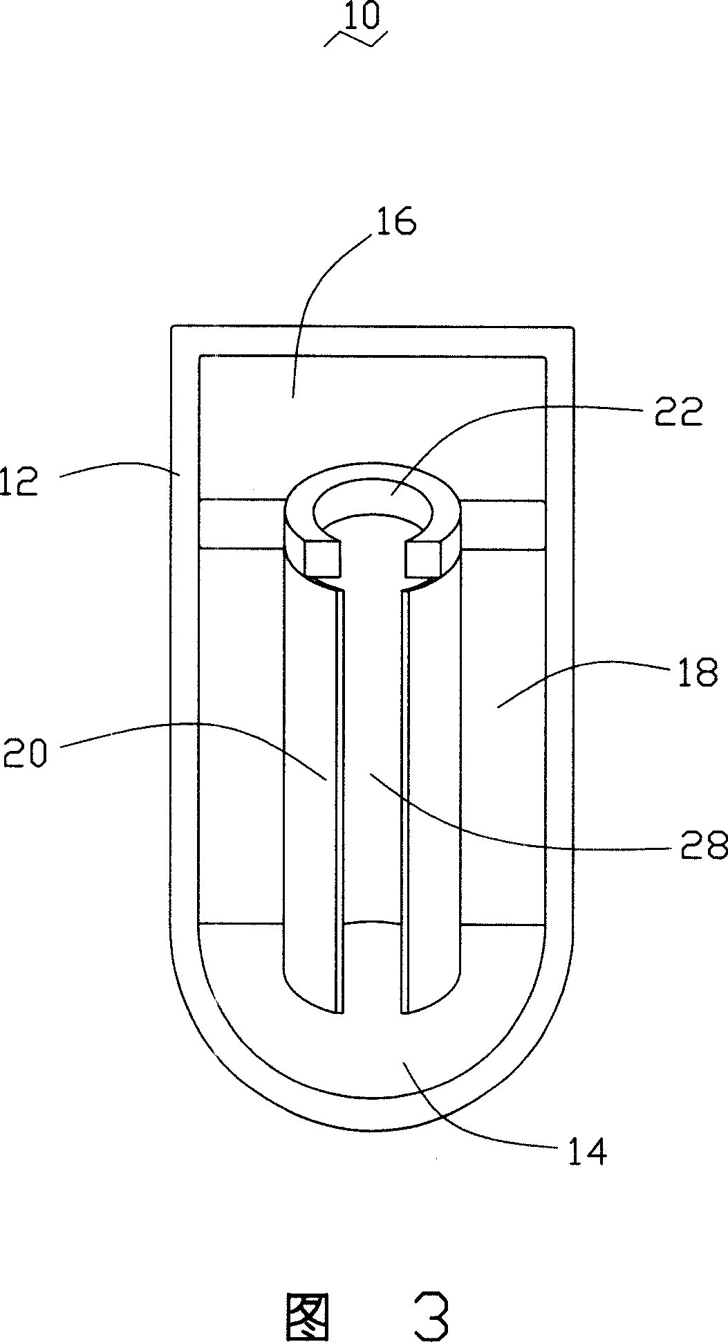
[0011] Please refer to FIG. 1 to FIG. 3 , the support frame 18 is arranged in an inclined shape, one end is formed on the base 12 , and the other end is a free end. The support frame 18 is provided with a cylindrical casing 20 along its length direction, and a strip-shaped opening 28 is defined on the top surface of the cylindrical casing 20 , the length of the opening 28 is equal to the length of the support frame 18 . The free end of the support frame 18 is also provided with a U-shaped protrusion 22 , and the height of the left and right sides of the U-shaped protrusion 22 is higher than the thickness of the support frame 18 . The storage groove 14 is placed on...


PUM


Abstract

An electric iron stand comprises a base, a supporter arranged in the oblique course of the base and a storage groove used for storing soldering tin that is arranged on the base. The supporter is provided with a cylinder case that is arranged in the direction of length. The cylinder case is used for holding an electric iron. The supporter is able to put the welding joint of the electric iron into the storage groove. Using the electric iron stand to hold the electric iron is convenient and safe, which not only can simplify the maintenance practice of the electric iron, but also can store solder.

Description

technical field [0001] The invention relates to an electric soldering iron frame. Background technique [0002] Generally, when it is desired to connect an electronic component to a circuit board or to electrically connect an electrical connector to a circuit board, it is usually soldered. Since the welding tip of the electric soldering iron is easy to be oxidized and damaged, it is necessary to add tin to the welding tip and melt it before doing the welding action, and then wipe it on a wet sponge to remove the oxide layer attached to the surface of the welding tip; to complete a certain part or After all the soldering operations, put the soldering iron back to the soldering iron stand. Because the temperature of the soldering tip is high, it is easy to hurt people or other objects, and the soldering iron cannot be placed at will. After the temperature of the soldering tip of the soldering iron drops, Add tin again to protect the soldering joint, and should not scrub it on...

Claims


Application Information

Patent Timeline
Patent Type & Authority Applications(China)
IPC IPC(8): B23K3/08H05K3/34
CPCB23K3/027
Inventor 郭斯蔚
Owner HONG FU JIN PRECISION IND (SHENZHEN) CO LTD
Why Eureka
Try Eureka