Joint track type walking mechanism

A traveling mechanism and crawler-type technology, applied in the field of articulated crawler traveling mechanism, can solve the problems of weakened load capacity, insufficient technical solutions, difficult adjustment, etc. Effect

Inactive Publication Date: 2008-03-19
DONGHUA UNIV
View PDF0 Cites 52 Cited by
  • Summary
  • Abstract
  • Description
  • Claims
  • Application Information

AI Technical Summary

Problems solved by technology

[0004] However, in the prior art, the common double-crawler walking mechanism still has the following obvious deficiencies: 1. It cannot independently cross obstacles, and before each crossing, manual intervention is required to adjust the posture of swinging legs before and after; 2. In the process of climbing, many times of manual intervention and multiple adjustments to the posture of swinging legs are required; 3. When climbing steps or stairs, the movements are not fast enough and flexible enough; 4. Although they have the ability to cross vertical obstacles to a certain extent, their The ability is still very limited, and the maximum height over obstacles is not high enough
[0008] It can be seen from the above introduction: 1. In the process of climbing over vertical obstacles, the existing mechanism must adjust the angle of the swing arm many times, so the climbing is not fast enough and flexible; 2. From the current public According to the report, in the prior art, manual intervention is required to adjust the swing angle of the swing arm when the ordinary double-track traveling mechanism climbs over vertical obstacles; if the swing angle of the swing arm can be automatically adjusted by circuit control in the future , then, the relevant control circuit will become very complicated, the difficulty will be greater, and the cost will increase; 3. In the process of climbing over the vertical obstacle, no matter how high or low the vertical obstacle is, the load of heavy objects in the existing mechanism 4. At a certain stage of climbing, such as the stage shown in Figure 24, the contact between the existing mechanism and the ground and obstacles is a line contact; because the contact area of ​​the line contact is small , the total friction force is also small, so the driving ability at this time is very poor, and slipping is easy to occur at the line contact. However, when climbing over vertical obstacles, due to the occurrence of line contact and slippage, its load capacity will also be greatly weakened.
Therefore, generally speaking, the load capacity of ordinary double crawler running gear is not high enough
[0009] In addition to the above-mentioned situation, in the prior art, various running gears including the common double-crawler running gear also have the following common deficiencies: 1. There are not many technical solutions available for selection. From the perspective of diversity, further expansion is needed; 2. When a vehicle or robot walks on terrain with slopes both vertically and horizontally, accidents such as overturning are prone to occur, that is to say, it is not possible to flexibly adjust the level of the vehicle body. Adjustment, or even if the levelness in the front and rear directions can be adjusted, it is difficult to adjust the levelness in the left and right directions of the running mechanism; 3. The size of the contact area with the ground cannot be adjusted, or it cannot be in large-area contact with the ground. Therefore, Can't do it: can walk flexibly on hard and flat roads, and can cross soft ground such as swamps; 4. It is often difficult to climb over complex terrain such as ditches
[0010] It should be pointed out that during the walking process of the vehicle or robot, if the load-bearing working surface of the vehicle body cannot maintain a good levelness, the loaded objects or personnel may have displacement, rolling, overturning, falling and other accidents; for In terms of carrying precision instruments and meters and cutting-edge scientific and technological devices, if it cannot maintain a high level, it is impossible to talk about

Method used


Image

  • Joint track type walking mechanism
  • Joint track type walking mechanism
  • Joint track type walking mechanism

Examples


Embodiment 1

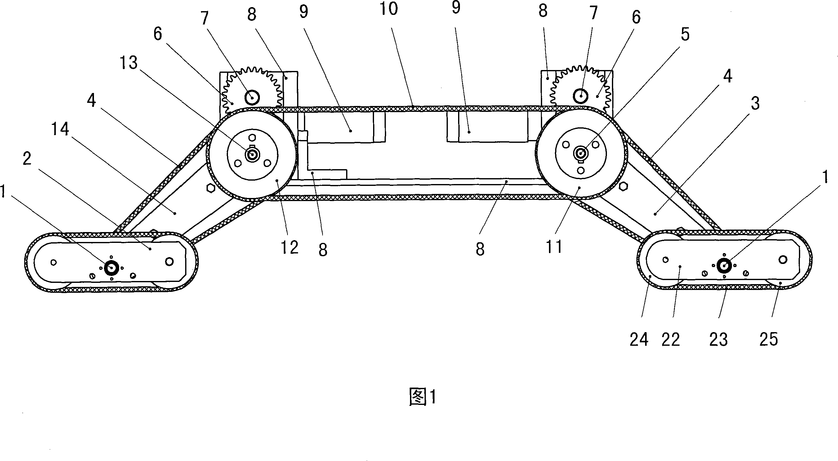
[0122] It will be described in conjunction with FIG. 7 , FIG. 18 and FIG. 19 . Fig. 7 is a schematic diagram of the crawler foot, Fig. 18 is a three-dimensional schematic diagram of the crawler foot, and Fig. 19 is a schematic diagram of the position of the rotary shaft of the crawler foot.

[0123] The labels in the figure will be explained first. 1 is the rotary shaft of the crawler foot, 22 is the foot support of the crawler, 23 is the walking crawler, 24 is the driving wheel of the crawler foot, 25 is the driven wheel of the crawler foot, 26 is the first gear (shown in dotted line), and 27 is the last gear (shown by the dotted line) Show), 28 is the second gear (shown in dotted line).

[0124]In this embodiment, the crawler foot transmission mechanism is composed of three gears meshing front and rear (shown by three dotted circles in Fig. 7), the first gear 26 is fixedly connected to the crawler foot rotary shaft 1, and the second gear 28 and crawler foot support 22 are ...

Embodiment 2

[0132] Description will be made in conjunction with FIG. 4 , FIG. 7 , FIG. 9 , FIG. 10 , FIG. 11 and FIG. 12 .

[0133] The labels in the figure will be explained first. 1 is crawler foot rotary shaft, 22 is crawler foot support, 23 is walking crawler belt, 24 is crawler foot driving wheel, 25 is crawler foot driven wheel, 26 is first gear, 27 is last gear, and 28 is second gear.

[0134] From the previous introduction and description, it can be known that one of the technical solutions of the present invention is that the axis position of the crawler foot rotary shaft 1 is low. angle, or even turn up to a 90° angle to climb over obstacles. How the running mechanism using this technical solution and other technical solutions works is further described below. In the walking mechanism of the present invention shown in Fig. 4, during the movement, the front end of the crawler foot 2 runs into the wall of the vertical obstacle, as shown in Fig. 9; The walking track 23 rotates a...

Embodiment 3

[0138] It will be described in conjunction with FIG. 13 , FIG. 14 , FIG. 15 , and FIG. 16 .

[0139] This embodiment introduces several obstacles that the running mechanism of the present invention can overcome.

[0140] Figure 13 is a crossing trench with a vertical wall in front and a slope in the back. The walking mechanism of the present invention can not only climb over, but also maintain good levelness all the time in the process of climbing over.

[0141] Figure 14 also crosses the ditch, but the front and rear of the ditch are all slopes. The walking mechanism of the present invention can not only climb over, but also maintain good levelness all the time in the process of climbing over. During the crawling process, the front track foot, synchronous track foot and rear track foot jointly participate in the drive.

[0142] Figure 15 is the situation when driving on swampy mud or soft ground. At this time, not only the crawler foot 2 is in contact with the ground, but ...


PUM


Abstract

The invention discloses a joint track type travel mechanism, which relates to the technical field of vehicles and robots. To solve low climbing obstacle capability and other problems, the following technical proposal is presented: a joint track type travel mechanism includes a vehicle body (8) and a circuit, and is characterized in that the joint track type travel mechanism also includes four track legs (2), a swing arm, two synchronous belts (10), two sets of drive worm and worm wheel (16), four sets of swing arm worm and worm wheel (17), two drive transmission shafts (5), four swing arm transmission shafts (7), two drive motors (15), four swing arm motors(9), four swing arm driving gears (6), two front synchronous pulleys (2), two rear synchronous pulleys (11) and two rotational shafts (13). The invention has the advantages that a travel mechanism with distinctive style and structure is provided, which has strong climbing obstacle capability, can independently, flexibly and quickly climb the stairs and terrace depending on the mechanical and structural characteristics of the travel mechanism, without manual interference.

Description

technical field [0001] The invention relates to the technical field of vehicles and robots, in particular to a articulated crawler-type walking mechanism. Background technique [0002] At present, scientific research institutions and related manufacturers at home and abroad have carried out a lot of research and trial development on the walking mechanism of vehicles or robots, and have also made many achievements and progress. However, in the existing technology, there are still many places that need to continue to innovate and improve. [0003] In the prior art, the ability of the common double-crawler traveling mechanism to cross obstacles is not strong, for example, it cannot cross vertical obstacles and the like. Compared with the ordinary double crawler walking mechanism, the ordinary joint crawler walking mechanism has significantly improved the ability to cross obstacles and has the ability to cross vertical obstacles. [0004] However, in the prior art, the common ...

Claims


Application Information

Patent Timeline
Patent Type & Authority Applications(China)
IPC IPC(8): B62D55/065
Inventor 毛立民林申李锐陈文金韬于海涛王治国邹剑杨琳
Owner DONGHUA UNIV
Why Eureka
Try Eureka