Method for optimizing nozzle of a internal combustion engine

A technology of internal combustion engines and nozzles, applied in multi-objective optimization, fuel injection devices, mechanical equipment, etc., can solve problems such as failure

Inactive Publication Date: 2008-03-19
MAN ENERGY SOLUTIONS SA
View PDF9 Cites 4 Cited by
  • Summary
  • Abstract
  • Description
  • Claims
  • Application Information

AI Technical Summary

Problems solved by technology

[0007] Due to the high complexity of the relationships, such a sequential approach will often not be successful

Method used


Image

  • Method for optimizing nozzle of a internal combustion engine

Examples


Embodiment Construction

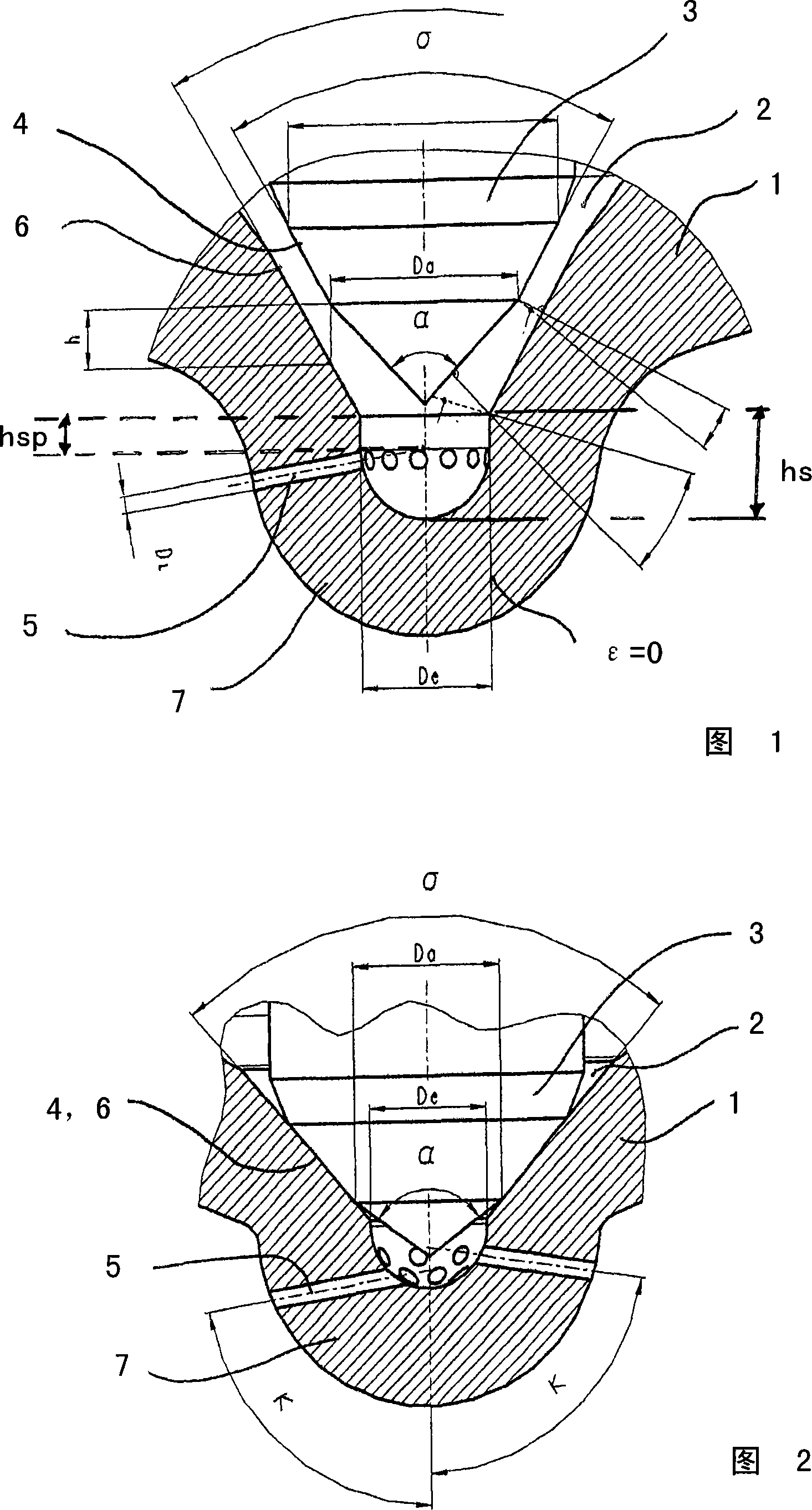
[0025] The invention relates to a method for optimizing a nozzle of an internal combustion engine comprising a nozzle body 1 and a nozzle needle 3 which can be moved axially against a closing force in a bore 2 of the nozzle body 1, wherein the nozzle needle 3 is on the combustion chamber side thereof There is a valve sealing surface 4 on the end face of the nozzle needle, in order to control the flow cross-section to at least one nozzle opening 5 introduced into the combustion chamber of the internal combustion engine, the nozzle needle cooperates with the valve seat surface 6 of the nozzle body 1 with the valve sealing surface, wherein for the nozzle For the geometrical modeling, a mathematical method in the form of particle swarm optimization (PSO) is used and referenced in the structural design of the nozzle as a criterion for the best attainment, using arbitrarily chosen individual parameters.

[0026] In a particularly preferred manner, the described optimization using PSO...


PUM


Abstract

The invention relates to a method for optimizing a nozzle of an internal combustion engine comprising a nozzle body (1) and a nozzle needle (3) which can be moved axially against a closing force in a bore (2) of the nozzle body (1), wherein , the nozzle needle (3) has a valve sealing surface (4) on its end face on the combustion chamber side. The seat surface (6) of the nozzle body (1) acts together, wherein for the geometry of the nozzle, a mathematical method in the form of particle swarm optimization (PSO) is used with arbitrarily chosen independent parameters and in the design of the nozzle The structure is referenced as a criterion for optimization calculations.

Description

technical field [0001] The invention relates to a method for optimizing a nozzle of an internal combustion engine according to the preamble of claim 1 . Background technique [0002] As is known, a nozzle comprises a nozzle body and a nozzle needle which can move axially against a closing force in the bore of the nozzle body, the nozzle needle having a valve sealing surface on its end face on the combustion chamber side, in order to control at least Flow cross-section of a nozzle opening with which the nozzle needle interacts with the valve sealing surface with the valve seat surface of the nozzle body. The nozzles are inserted into a nozzle holder, at the upper end of which, as is known, a spray line is connected. In the pressure chamber in the nozzle body, the fuel acts on the beveled shoulder of the nozzle needle and opens it against a closing force, which is usually induced hydraulically or by spring force. [0003] Common nozzles are, for example, so-called Lochdse no...

Claims


Application Information

Patent Timeline
Patent Type & Authority Applications(China)
IPC IPC(8): F02M61/16G06F17/50G06F19/00
CPCF02M61/1846G06F2217/08F02M61/168F02M61/182G06F17/5095G06F30/15G06F2111/06G06F30/00F02M61/10F02M61/18
Inventor H·格罗塞-洛谢H·哈伯兰德H·亚尔辛
Owner MAN ENERGY SOLUTIONS SA
Why Eureka
Try Eureka