Transformer conducting bar and winding leads connection structure

A winding lead wire and connection structure technology, applied in the direction of transformer/inductor coil/winding/connection, etc., can solve the problems of increased sealing difficulty, transformer oil leakage, etc., and achieve the effects of simple wiring, reduced leakage, and convenient maintenance

Inactive Publication Date: 2008-03-19
SHANDONG DACHI ELECTRIC
View PDF0 Cites 5 Cited by
  • Summary
  • Abstract
  • Description
  • Claims
  • Application Information

AI Technical Summary

Problems solved by technology

The disadvantages of this method are: for each maintenance or wiring, the transformer oil inside the box needs to be drained to make the oil level lower than the lead wire connection hand hole window to prevent the transformer oil from overflowing; the second is to pre-open holes on the side of the transformer box cover , which increases the difficulty of subsequent sealing and easily causes transformer oil leakage

Method used


Image

  • Transformer conducting bar and winding leads connection structure
  • Transformer conducting bar and winding leads connection structure
  • Transformer conducting bar and winding leads connection structure

Examples


Embodiment Construction

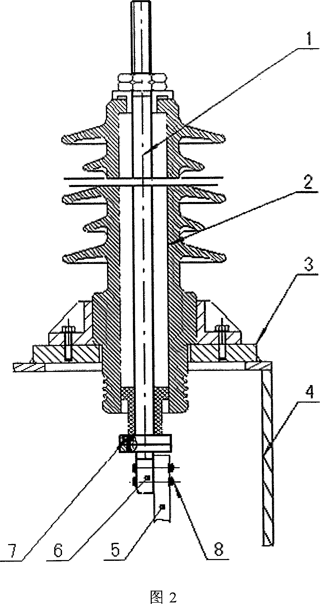
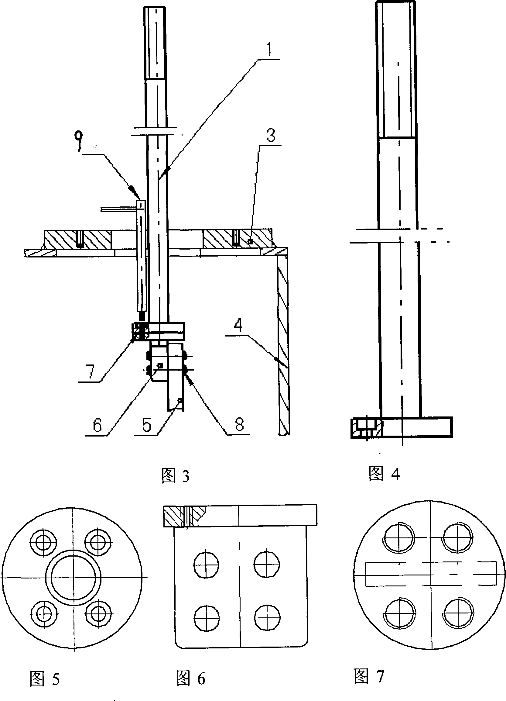
[0010] Accompanying drawing 2-7 is a kind of specific embodiment of the present invention.

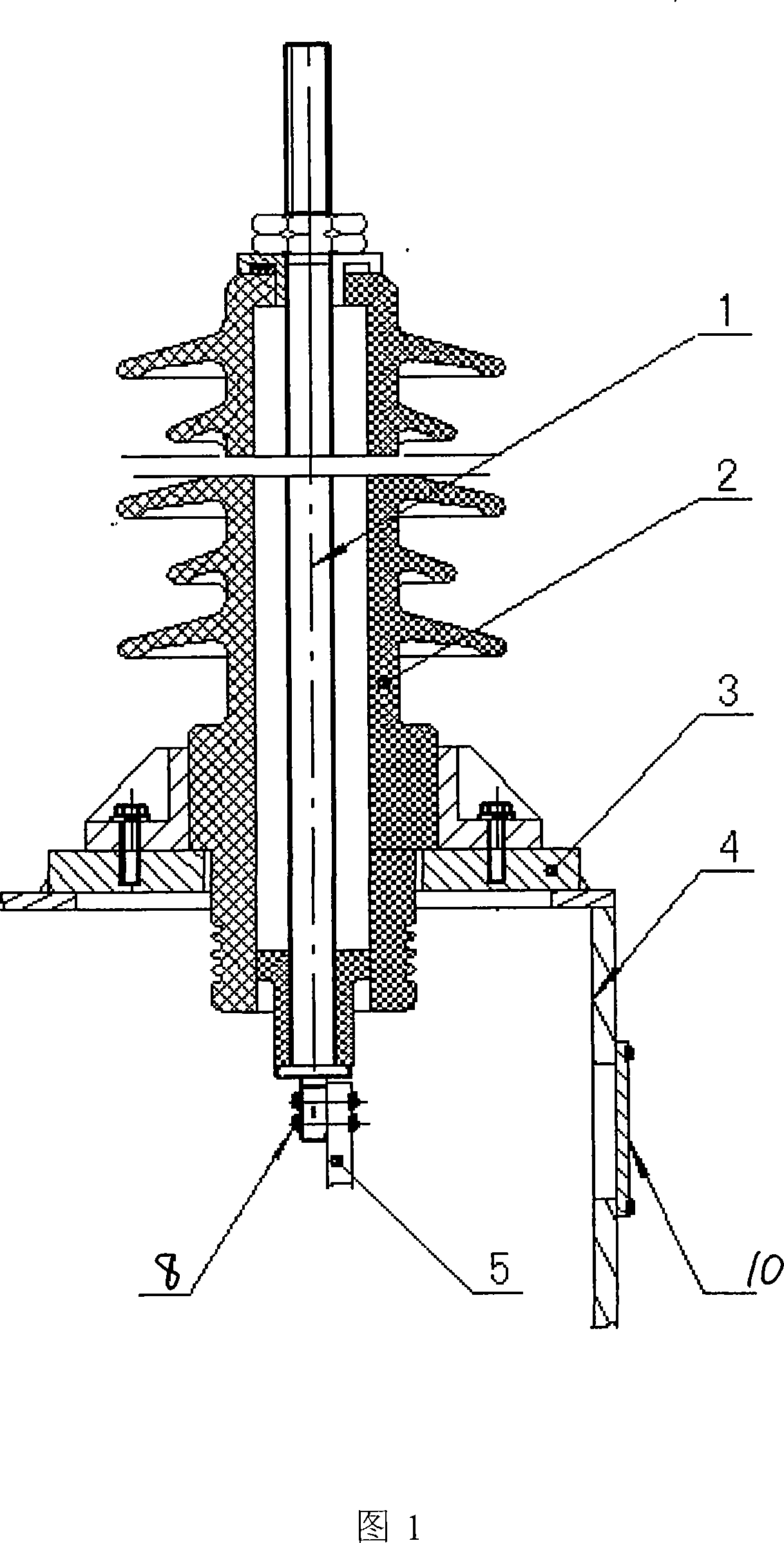
[0011] The connection structure of the transformer conductive rod and the winding lead wire of the present invention includes a lead wire connection plate 6 connected between the conductive rod 1 and the winding lead wire 5. The lead wire connection plate is composed of two mutually perpendicular flanges fixed as one. The conductive rod The lower end of 1 is provided with the flange corresponding to lead wiring board. For ease of use, one of the two flanges of the lead wiring board 6 is circular and the other is square, and one end of the square flange is connected to the middle of the circular flange. The flange at the lower end of the conductive rod is a circular flange.

[0012] In the connection structure of the transformer conductive rod and the winding lead wire of the present invention, when the winding is in place in the lower box body, the ends of the winding lead wire 5 are ...


PUM


Abstract

The invention provides a connection structure of a conductive rod and a winding lead of a transformer and is characterized in that the structure comprises a lead wiring board which is connected between the conductive rod and the winding lead and which is formed by two flanges vertical to each other and fixed integrally as a whole, and a flange provided at the bottom end of the conductive rod in opposite to the lead wiring board. The invention has the advantages of simple wire connection, no need of a lead connection hand hole on the lateral side of the transformer cover, reduced seal area of the transformer tank, reduced leakage of transformer oil, convenient maintenance, and no need of oil discharge from the transformer tank.

Description

(1) Technical field [0001] The invention relates to a connection structure between a transformer conductive rod and a winding lead wire. (2) Background technology [0002] At present, the existing transformers generally include a box body with a box cover, a winding is arranged in the box body, a bushing 2 and a conductive rod 1 inside the bushing are installed on the box cover, and the lower end of the conductive rod is connected to the winding lead 5 . At this stage, the connection between the winding lead wire 5 and the conductive rod 1 (see Figure 1) is through the pre-opened lead wire connection hand hole on the side wall 4 of the box cover after the sleeve 2 and the conductive rod 1 are fixed in place, using bolts 8 connection, and then adopt the cover plate 10 to seal the lead wire connection hand hole that is opened in advance on the side of the case cover. The disadvantages of this method are: for each maintenance or wiring, the transformer oil inside the box need...

Claims


Application Information

Patent Timeline
Patent Type & Authority Applications(China)
IPC IPC(8): H01F27/29
Inventor 白峰君马立明许长华
Owner SHANDONG DACHI ELECTRIC
Why Eureka
Try Eureka