Design method of single-tube electrolytic tank

A design method and electrolytic cell technology, which can be applied to electrolytic components, electrolytic processes, cells, etc., can solve the problems of a large number of fastening bolts, inconvenient installation, disassembly and maintenance, and complex combined structure, so as to achieve non-deformation and displacement, convenient assembly and disassembly, Good anti-knock effect

Active Publication Date: 2011-04-13
SHAANXI HUAQIN NEW ENERGY TECH CO LTD
View PDF5 Cites 2 Cited by
  • Summary
  • Abstract
  • Description
  • Claims
  • Application Information

AI Technical Summary

Problems solved by technology

[0005] Because the pole plate is installed in the installation groove of the insulating support plate, there is an installation gap. Once the electrolytic cell implodes, the pole plate is deformed and detached from the groove, so the anti-knock performance is poor
[0006] The combination structure of the device is relatively complicated, the sealing area is large, the number of fastening bolts is large, and it is inconvenient to install, disassemble and maintain

Method used


Image

  • Design method of single-tube electrolytic tank
  • Design method of single-tube electrolytic tank
  • Design method of single-tube electrolytic tank

Examples


Embodiment 1

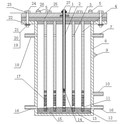
[0024] A design method for a single-tube electrolytic cell is composed of five tubular electrodes 4 with different tube diameters and arranged at equal intervals between a circular anode 2 and a tubular cathode 8; It is a single-tube tank body whose diameter is larger than that of other tubular electrodes 4 and circular anode 2, and the circular anode 2 is arranged at the center of the tank body; the circular anode 2 is tubular or cylindrical.

Embodiment 2

[0026] A design method for a single-tube electrolytic cell is composed of a circular anode 2 and a tubular cathode 8 with two tubular electrodes 4 with different diameters and equally spaced sets of tubular electrodes 4 arranged sequentially; the tubular cathode 8 It is a single-tube tank whose diameter is larger than that of other tubular electrodes 4 and circular anode 2, and the circular anode 2 is arranged in the center of the tank; the circular anode 2 is tubular (or cylindrical) . The circular anode 2 is made of low-carbon steel pipe (or low-carbon steel column), and its surface is plated with a nickel layer; the tubular cathode 8 and the tubular electrode 4 are both made of low-carbon steel pipe, and their steel pipe surfaces are blasted deal with.

Embodiment 3

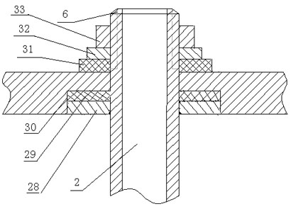
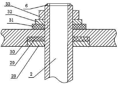
[0028] A design method for a single-tube electrolytic cell is composed of a circular anode 2 and a tubular cathode 8, and eight tubular electrodes 4 with different tube diameters and arranged at equal intervals are sequentially nested; the tubular cathode 8 It is a single-tube tank whose diameter is larger than that of other tubular electrodes 4 and circular anode 2, and the circular anode 2 is arranged in the center of the tank; the circular anode 2 is tubular (or cylindrical) . The upper end of the tubular electrode 4 is provided with an end plate insulating rubber pad 25 with an annular groove, and the lower end is provided with an insulating rubber pad 12 with an annular groove. The tubular electrode 4 is embedded in the end plate insulating rubber pad 25 and the insulating rubber pad with an annular groove. In the annular groove of pad 12.


PUM


Abstract

The invention relates to a water electrolysis hydrogen-oxygen generation device, in particular to a design method of a single-tube electrolytic tank. The electrolytic tank is characterized by being formed by sleeving two to eight tubular electrodes (4) with different tube diameters between a round anode (2) and a tubular cathode (8) at intervals in turn, wherein the tubular cathode (8) is a single-tube tank body, and the diameter of the tubular cathode (8) is greater than the diameters of other tubular electrodes (4) and the round anode (2); and the round anode (2) is arranged at the central position of the tank body and is tubular or cylindrical. The invention has the characteristics that: the electrolytic tank has high anti-detonating property and sealing performance, a small sealing surface, a simple structure and low cost, and is convenient to assemble and disassemble, electrolyte is difficult to leak, and the like.

Description

technical field [0001] The equipment of the present invention relates to a hydrogen-oxygen generating device for water electrolysis, in particular to a design method of a single-tube electrolyzer. Background technique [0002] The Chinese patent titled "Automatic Water Electrolysis Generator" with application number 200520078715.5 discloses a combined electrolytic cell, which consists of more than two conductive boxes, the conductive box basket, the anode plate and the cathode plate, A rubber gasket is combined between the anode plate and the conductive box body basket. There are insulating support plates around the inside of the conductive box basket, more than two pole plates are installed in the installation groove of the insulating support plate, and an insulating lining is provided between the insulating support plate and the conductive box basket. The cathode plate, the insulating pad, the conductive box body basket, the insulating pad and the anode plate are combined...

Claims


Application Information

Patent Timeline
Patent Type & Authority Applications(China)
IPC IPC(8): C25B9/06C25B9/17
Inventor 折生阳孙纪州王彦东陈仁治霍佳明夏文武李建庄新东
Owner SHAANXI HUAQIN NEW ENERGY TECH CO LTD
Why Eureka
Try Eureka