Pressurization type mechanical glue-pouring machine

A glue filling machine and mechanical technology, which is applied in the direction of structural parts, electrical components, battery pack parts, etc., can solve the problems of glue overflow, easy blockage of glue filling ports, and large waste, so as to improve the quality of glue filling and reduce waste of glue , high perfusion efficiency

Inactive Publication Date: 2008-03-19
江苏华富能源有限公司
View PDF0 Cites 2 Cited by
  • Summary
  • Abstract
  • Description
  • Claims
  • Application Information

AI Technical Summary

Problems solved by technology

However, due to the high viscosity of the colloidal electrolyte, it is easy to block the glue filling port and difficult t

Method used


Image

  • Pressurization type mechanical glue-pouring machine

Examples


Example Embodiment

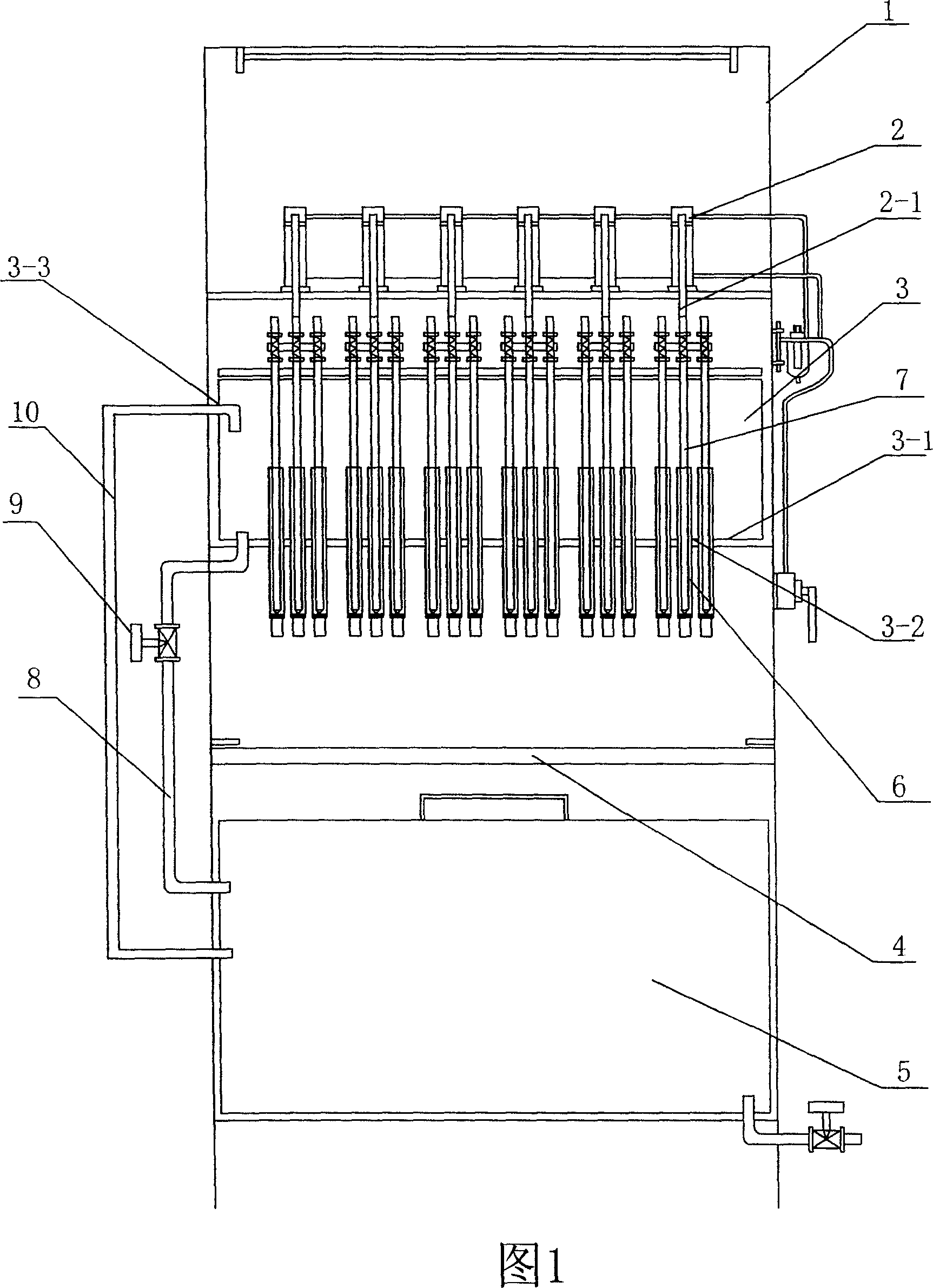
[0011] As shown in the figure, a cylinder 2, a glue storage tank 3, a workbench 4, and an acid tank 5 are arranged on the frame 1 from top to bottom. The free end of the piston rod 2-1 of the cylinder 2 is arranged downward. A rubber feeding pipe 8 is connected between the acid tank 5 and the glue storage tank body 3, and a regulating valve 9 is connected in series to the rubber feeding pipe 8. An outlet 3-3 for controlling the highest level of the colloid is provided on the glue storage tank 3, and an overflow pipe 10 is connected between the outlet 3-3 and the acid tank 5.

[0012] A through hole 3-2 is opened on the lower bottom plate 3-1 of the glue storage box 3, and the through hole 3-2 is sealed and connected to the vertically arranged syringe-shaped acid cup 6, and a pusher is arranged in the syringe-shaped acid cup 6. The upper end of the rod 7 and the push rod 7 is connected with the piston rod 2-1 of the cylinder 2.

[0013] The workbench 4 is arranged below the syringe...


PUM


Abstract

A compression-type mechanical glue dispenser is provided, which relates to the mechanical equipment for producing lead-acid accumulators, particularly the technique of glue dispensing equipment. A cylinder and a glue storage box are both provided on a frame. The cylinder is arranged above the glue storage box. The bottom plate of the glue storage box is provided with a through hole. A syringe-like acid cup is vertically equipped on and hermetically connected with the through hole. A pusher is equipped inside the syringe-like acid cup, and the top end of the pusher is connected with a piston rod of the cylinder. The inventive glue dispenser has the advantages that the efficiency of glue dispense is high; since the syringe-like acid cup is sized according to the glue consumption, to completely avoid the overflow of glue, reduce the waste of glue and improve the glue dispersion quality; and the operator can rapidly and easily complete the glue dispense operation by controlling the cylinder.

Description

Technical field [0001] The invention relates to mechanical equipment for the production of lead-acid batteries, in particular to the technology of glue filling equipment. Background technique [0002] With the technological advancement of lead-acid batteries, the technology of colloidal lead-acid batteries is becoming more mature, and the market demand is large. The existing glue filling method is to align the lower end of the funnel-shaped acid cup with the glue injection port of the battery box in turn, and pour glue into the battery box through the self-weight of the glue. However, due to the high viscosity of the colloidal electrolyte, it is easy to block the glue filling port and difficult to fill. Not only the filling efficiency is low, but also a large amount of glue overflows and the waste is large. Summary of the invention [0003] The purpose of the present invention is to design a pressurized mechanical glue filling machine to improve glue filling efficiency and reduc...

Claims


Application Information

Patent Timeline
IPC IPC(8): H01M2/36H01M50/609H01M50/673
CPCY02E60/12Y02E60/10
Inventor 居春山
Owner 江苏华富能源有限公司
Why Eureka
Try Eureka