
Ultrasound flow meter

A flowmeter and flow-through technology, which is applied in the field of flowmeters, can solve problems such as false measurement results, asymmetry or radial interference, and achieve good measurement results and improve measurement accuracy.

Inactive Publication Date: 2008-03-26
HYDROMETER GMBH
View PDF1 Cites 15 Cited by
  • Summary
  • Abstract
  • Description
  • Claims
  • Application Information

AI Technical Summary

Problems solved by technology

Asymmetrical or radially disturbed flow profiles can occur inside the measuring section or in the inlet area, which lead to false measuring results

Method used


Image

  • Ultrasound flow meter
  • Ultrasound flow meter
  • Ultrasound flow meter

Examples


Embodiment Construction

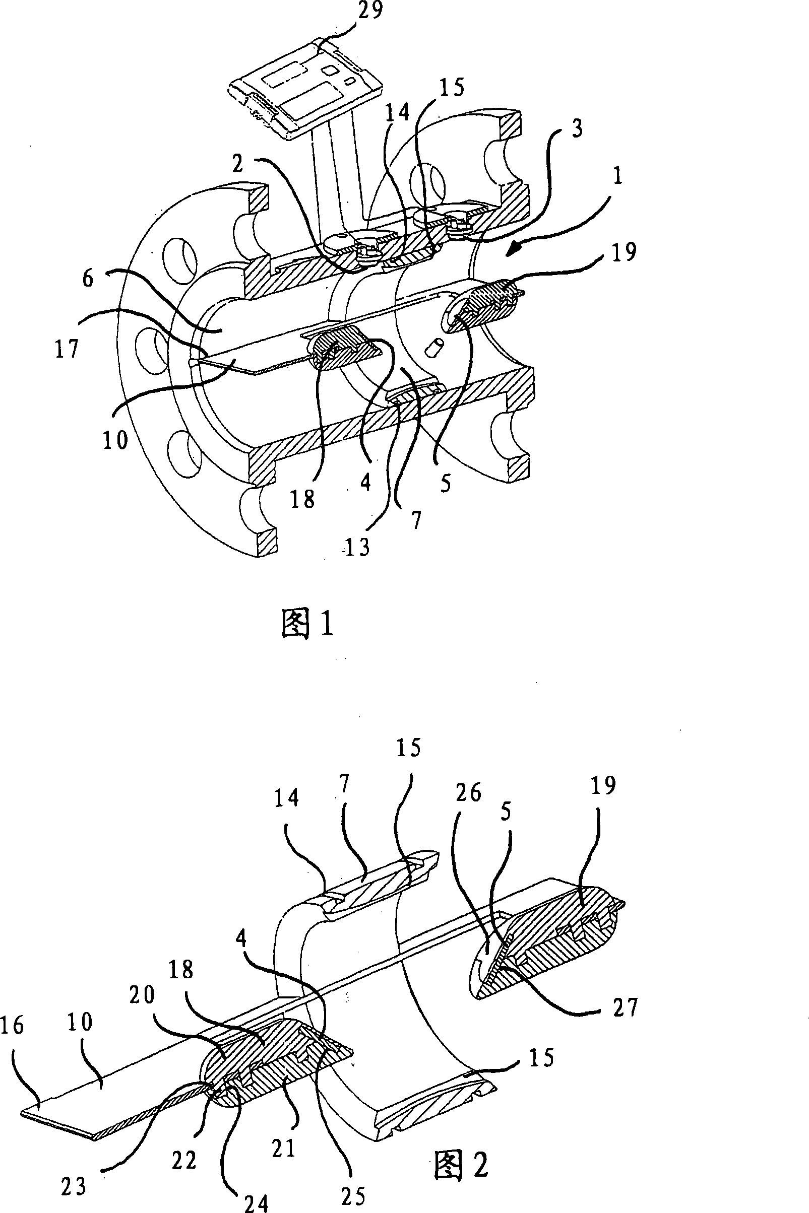
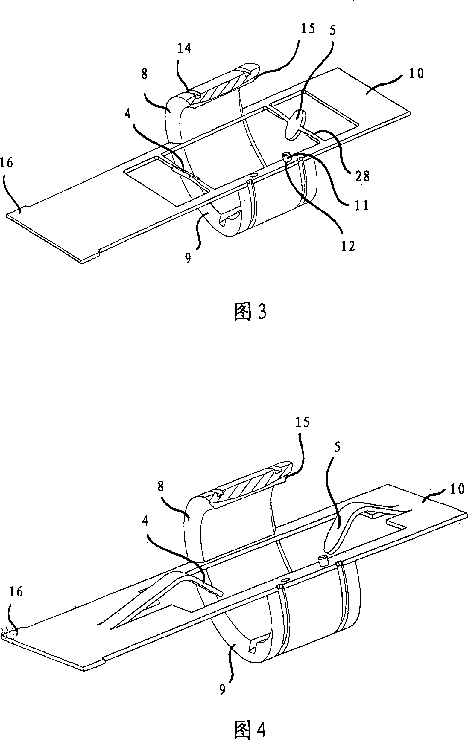
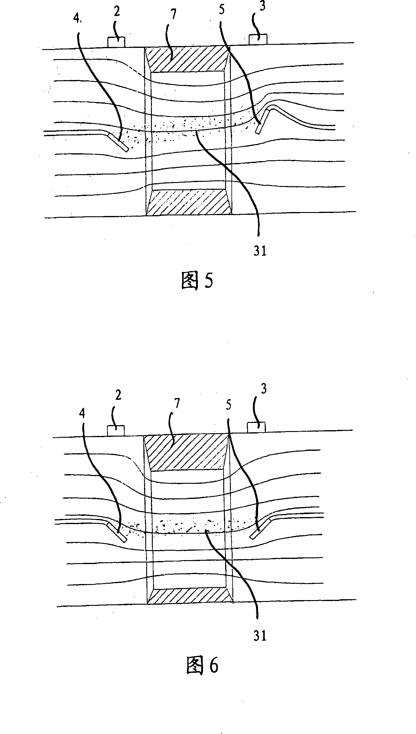
[0081] Figure 1 shows a flowmeter for a fluid or gaseous medium, which has a measuring channel 1 through which the medium flows, an inlet channel and an outlet channel and an ultrasonic transducer pair 2, 3 for transmitting or receiving ultrasonic signals , wherein a reflector pair 4 , 5 is provided in the measuring channel 1 for transmitting an ultrasonic signal from one ultrasonic transducer 2 to the other ultrasonic transducer 3 . The diameter of the measuring channel 1 is reduced locally, that is to say at the measuring section defined by the two reflectors 4 , 5 , for the conduction of the medium. The narrowing 7 is formed by a measuring channel insert arranged on the inner wall 6 of the measuring channel, which at the same time serves as a holding or fixing body for other functional components. A measuring channel ring is provided as the narrowing 7 .

[0082] The constriction 7 is responsible for squeezing the inflowing liquid and thereby accelerating the flow between ...


PUM


Abstract

The invention relates to a flow meter used in liquid or gas medium, which includes one measuring channel (1) flowed through medium, at least one inlet passage, at least one exit passage and at least one ultrasonic wave transducer couple pairs (2, 3), wherein, at least one reflector couple pairs (4, 5) is disposed in the measuring channel (1) for transporting one ultrasonic wave signal from one ultrasonic wave transducer (2 or 3) to another ultrasonic wave transducer (2 or 3). The diameter of the measuring channel (1) is decreased partly by one reduction part (7) to guide through flow, wherein, the reduction part (7) is comprised of insert of measuring channel disposed or combined on the inner wall (6) of the measuring channel, meanwhile the reduction part is keeper or stationary object for using in other functional parts. Furthermore, the invention also relates to a flow meter, wherein, one flow guide plate as fixed plate of reflector couple pairs extends upwards on the measuring channel. In another implementing case, at least two measuring sections are disposed, which includes at least one reflector couple pairs and one ultrasonic wave transducer couple pairs respectively.

Description

technical field [0001] The invention relates to a flow meter for liquid or gaseous media. Background technique [0002] For ultrasonic flow measurement, flow meters are known which have a measuring channel through which a medium flows and an inlet channel and an outlet channel, in which at least one ultrasonic transducer pair is used for transmitting or receiving ultrasonic signals. As described in DE 100 47 383 C1, in order to transmit an ultrasonic signal from one ultrasonic transducer to the other ultrasonic transducer, a reflector pair is arranged in the measuring channel, thereby realizing a U of the ultrasonic signal. shape turn. Asymmetrical or radially disturbed flow profiles can arise within the measuring section or in the inlet region, which lead to false measuring results. [0003] It is also known that the diameter or the cross section of the measuring channel is reduced at least in regions for the flow guidance in order to obtain a sufficiently high flow veloc...

Claims


Application Information

Patent Timeline
Patent Type & Authority Applications(China)
IPC IPC(8): G01F1/66G01P5/24
CPCG01F1/662
Inventor 哈拉尔德·克勒默威廉·奥菲莱因京特·豪恩施泰因
Owner HYDROMETER GMBH
Learn More