Backlight drive method

A technology of backlight and light source, which is applied in the field of driving backlight, and can solve problems such as dizziness and reduced visual quality

Inactive Publication Date: 2008-03-26
AU OPTRONICS CORP
View PDF0 Cites 17 Cited by
  • Summary
  • Abstract
  • Description
  • Claims
  • Application Information

AI Technical Summary

Problems solved by technology

[0006] In addition to reducing the visual quality of the color separation phenomenon, there are als...

Method used


Image

  • Backlight drive method
  • Backlight drive method
  • Backlight drive method

Examples


Embodiment Construction

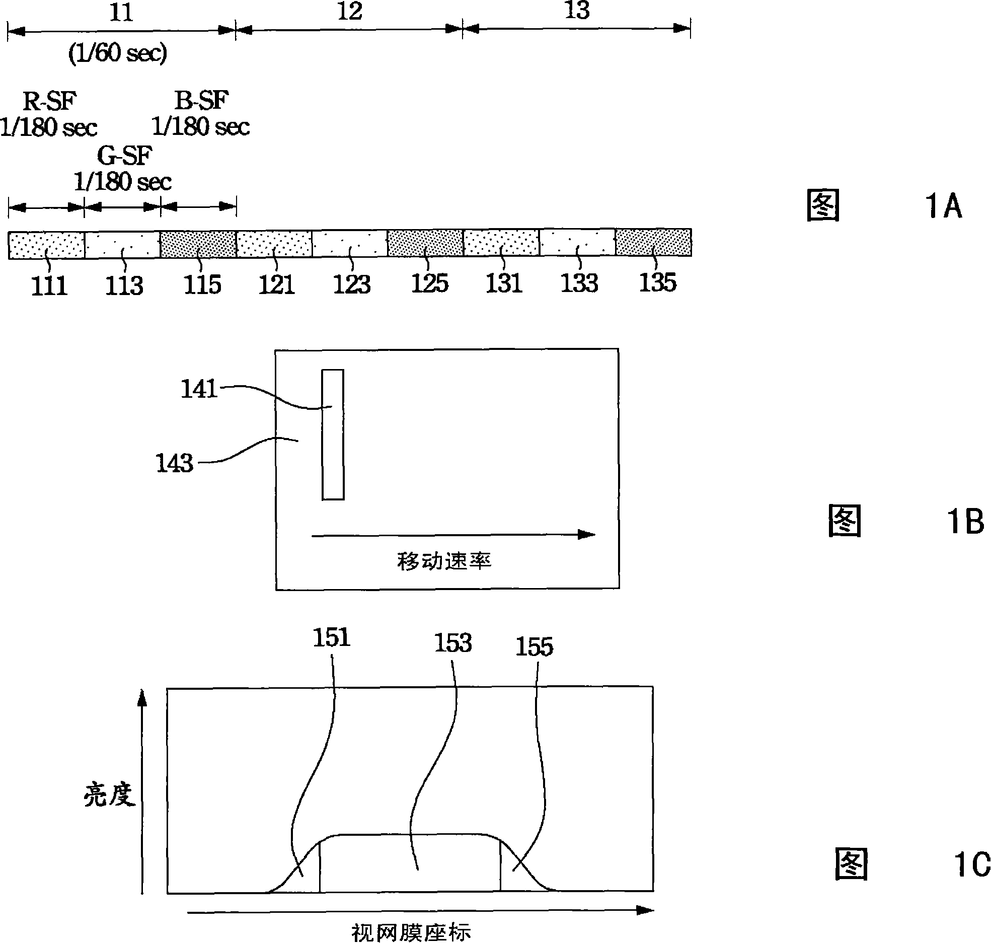
[0021] The present invention adopts changing the order of the color field: changing the order of the color field in each image arbitrarily, so that the order of the color separation stripes is no longer fixed, and the periodicity of the appearance of the color separation stripes is destroyed, reducing the degree of attention.

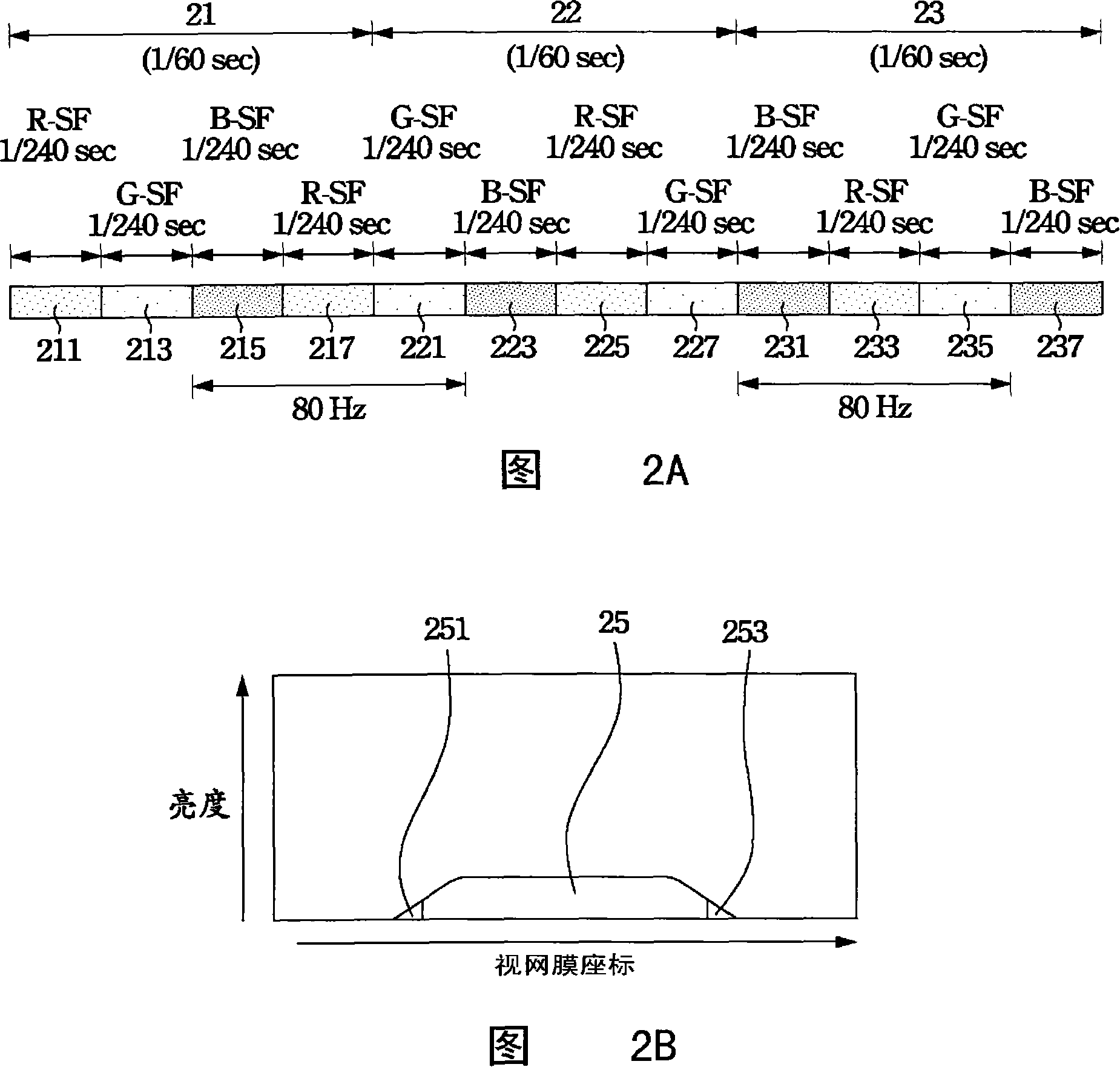
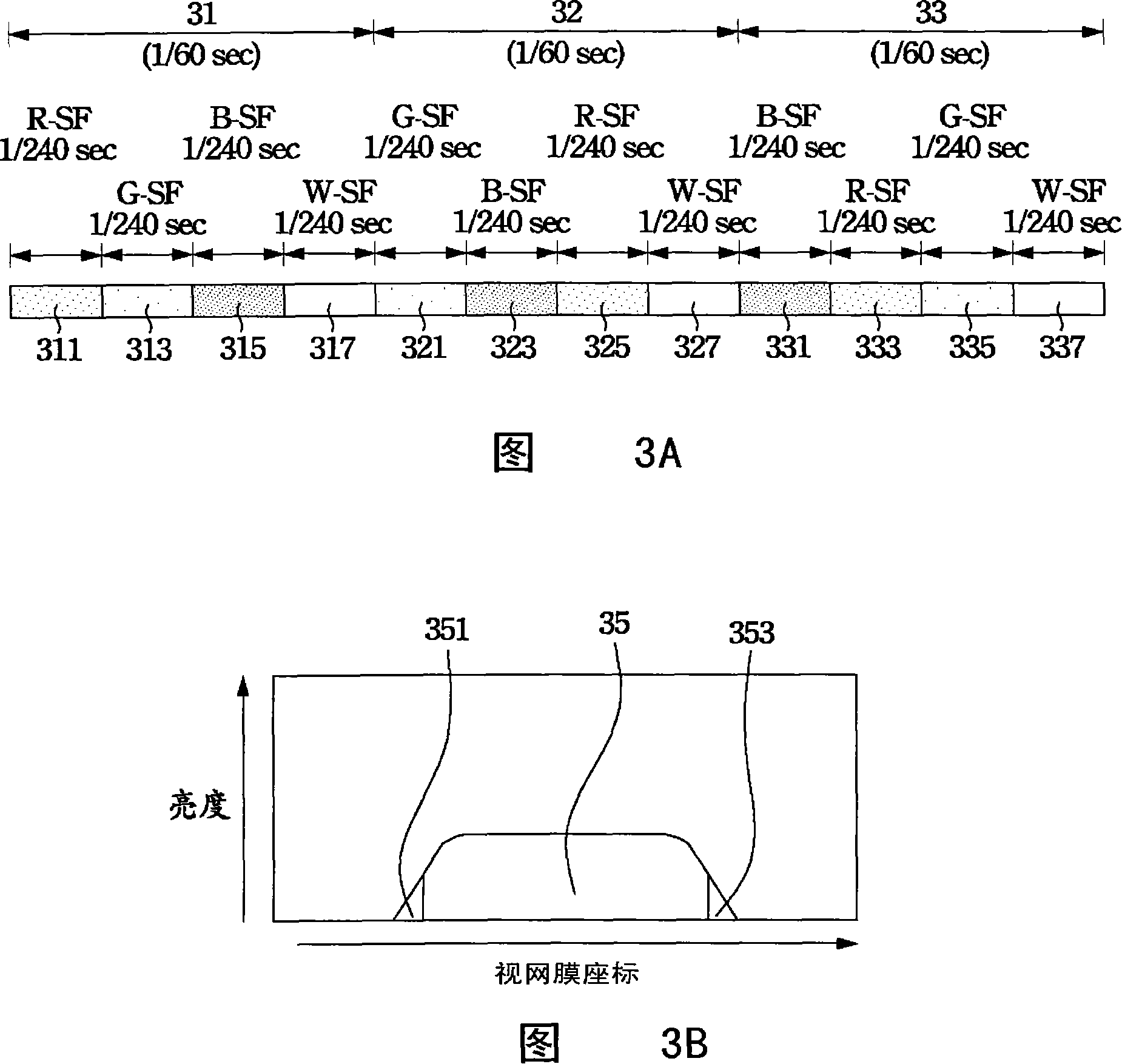
[0022] When the frequency of the green subfield is lower than 50 Hz, human eyes will perceive flickering. Under the principle of not destroying the edge color complementarity of the color sequence method, by increasing the sub-color field or inserting the frequency of the white sub-color field to compensate for the flicker phenomenon perceived by the human eye, the color separation phenomenon can be effectively suppressed and the brightness of the picture can be increased. Embodiments of the present invention will be explained in detail below.

[0023] In the first embodiment, as shown in Figure 2A, it is a driving method for a backlight source (not sho...


PUM


Abstract

The method for driving back lights comprising red light, blue light and green light includes: dividing a picture displaying area into four sub-areas, the green light is lighted twice respectively in two sub-areas of the first picture-displaying area; the three lights are lighted respectively in a first order in the four sub-areas of the first picture-displaying area, and lighted respectively in a second order in the second picture-displaying area. In which, the first order is different from the second order.

Description

【Technical field】 [0001] The invention relates to a method for driving a backlight source, which improves the color separation phenomenon of the color sequence method by changing the arrangement of the turn-on sequence of the light sources. 【Background technique】 [0002] The existing color-sequential liquid crystal display technology utilizes the method of temporal color mixing to generate various color pictures. As shown in Figure 1A, the method is to divide a picture interval 11 into a first sub-interval 111, a second sub-interval 113, and a third sub-interval 115, and turn on the red light source in the first sub-interval 111, and turn on the red light source in the second sub-interval. 113 turning on the green light source alone and turning on the blue light source in the third sub-interval 115 . The sequence of turning on the light sources is as described above, and the individual three-color light sources are also turned on in the second picture sub-section 12 and th...

Claims


Application Information

Patent Timeline
IPC IPC(8): G09G3/34G09G3/36G09G5/02G02F1/133H05B37/02
Inventor 许雅婷林芳正黄乙白谢汉萍陈建宏洪集茂
Owner AU OPTRONICS CORP
Why Eureka
Try Eureka