Liquid crystal display possessing source cathode drive and data transmission method
A source driver and liquid crystal display technology, applied in static indicators, instruments, etc., can solve the problems of high cost of liquid crystal display, high load of timing controller, large layout area, etc.
- Summary
- Abstract
- Description
- Claims
- Application Information
AI Technical Summary
Problems solved by technology
Method used
Image
Examples
no. 1 example
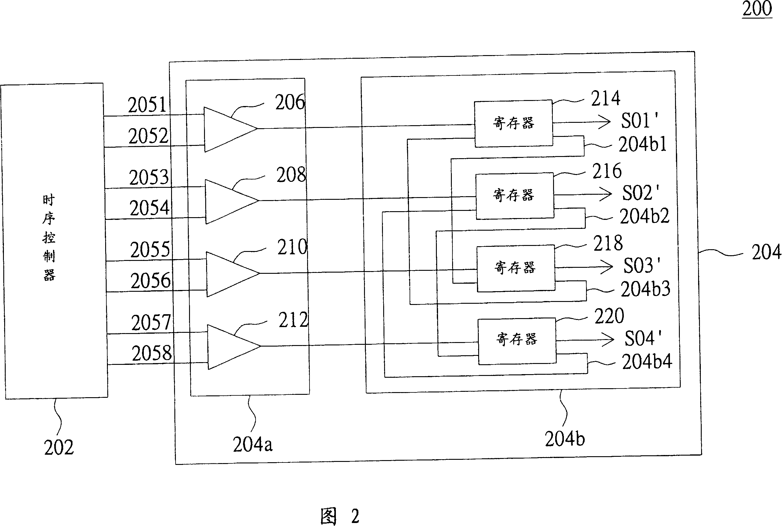
[0041]Please refer to FIG. 3A , which shows a circuit connection diagram of the timing controller 202 and the source driver 204 when the source driver 204 operates in the first mirroring operation mode. When the source driver 204 operates in the first mapping mode, the receiving units 210, 212 and the transmission paths 204b3, 204b4 are disabled (at this time, the disabled receiving units 210, 212 and the transmission paths 204b3, 204b4 are indicated by dotted lines ), and the transmission paths 204b1 and 204b2 are enabled. In this way, the timing controller 202 can only output the red sub-pixel data to the receiving units 206 and 208 through the buses 2051 - 2054 , and the registers 214 and 216 are respectively coupled in series with the registers 218 and 220 .
[0042] Please refer to FIG. 3B , which shows a timing diagram of bit data on the buses 2051 - 2054 when the source driver 204 operates in the first mapping operation mode.
[0043] At the rising edge (Rising Edge) o...
no. 2 example
[0060] Please refer to FIG. 6A , which shows a circuit connection diagram of the timing controller 202 and the source driver 204 when the source driver 204 operates in the second mirroring operation mode. Wherein, the source driver 204 operating in the second mapping operation mode is different from the source driver 204 operating in the first mapping operation mode in that the non-enabled receiving unit and the data transmission path are different, and at the same time, through different The bus to receive the bit data Bit0-Bit7 output by the timing controller 202. When the source driver 204 operates in the second mapping operation mode, the receiving units 206 and 208 and the transmission paths 204b1 and 204b2 are disabled (at this time, the disabled receiving units 206, 208 and the transmission paths 204b3 and 204b4 are denoted by dashed lines express). And the transmission paths 204b3 and 204b4 are enabled.
[0061]Please refer to FIG. 6B , which shows a timing diagram o...
PUM
 Abstract
Description
Claims
Application Information
 - R&D
- Intellectual Property
- Life Sciences
- Materials
- Tech Scout
- Unparalleled Data Quality
- Higher Quality Content
- 60% Fewer Hallucinations
Browse by: Latest US Patents, China's latest patents, Technical Efficacy Thesaurus, Application Domain, Technology Topic, Popular Technical Reports.
© 2025 PatSnap. All rights reserved.Legal|Privacy policy|Modern Slavery Act Transparency Statement|Sitemap|About US| Contact US: help@patsnap.com


