
LED and its making method

A technology of light-emitting diodes and light-emitting elements, which is applied to optics, condenser lenses, optical elements, etc., can solve problems such as affecting the light-emitting effect of the backlight module 10, yellowing, and affecting the quality of the backlight module 10.

Inactive Publication Date: 2008-03-26
HONG FU JIN PRECISION IND (SHENZHEN) CO LTD +1
View PDF0 Cites 0 Cited by
  • Summary
  • Abstract
  • Description
  • Claims
  • Application Information

AI Technical Summary

Problems solved by technology

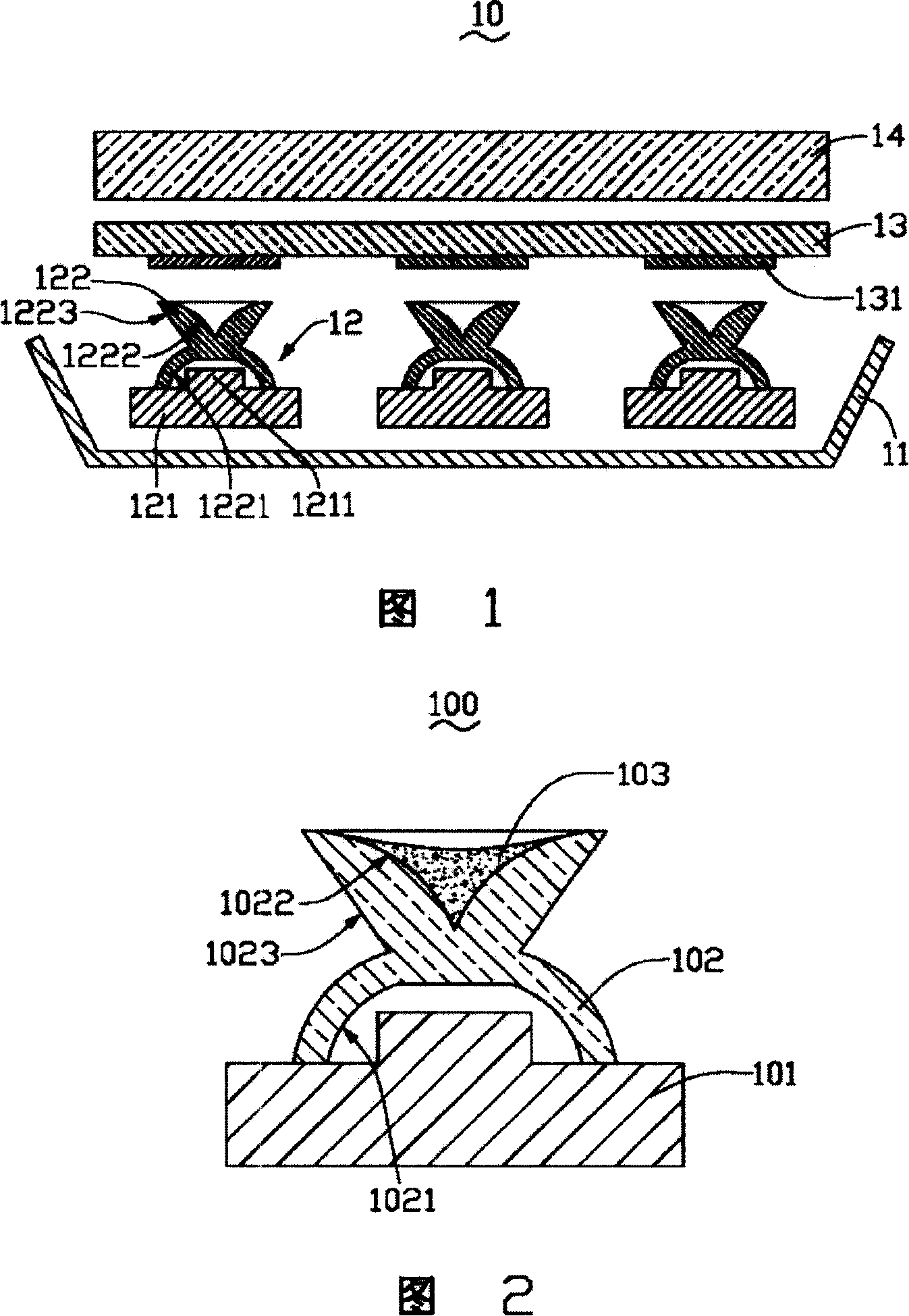
[0004] Although the top surface 1222 of the light guide prism 122 can totally reflect some of the incident light rays that satisfy the total reflection conditions, there are still many light rays that do not meet the total reflection conditions, and will exit to the Optical sheet 14; in order to prevent the part of the light entering the optical sheet 14 from forming a bright spot directly above the light-emitting diode 12 and affecting the luminous effect of the backlight module 10, a transparent plastic sheet containing a reflective sheet 131 needs to be provided between the optical sheet 14 and the light source plate 13, to reduce the intensity of light that can be incident on the optical sheet 14 at this part
However, the use of the transparent plastic plate 13 not only tends to increase the cost of the backlight module 10, but also the transparent plastic plate 13 may produce yellowing during use and affect the quality of the backlight module 10; Consider the alignment problem of reflector 131 and LED 12

Method used


Image

  • LED and its making method
  • LED and its making method
  • LED and its making method

Examples


Embodiment Construction

[0017] The light-emitting diode and its preparation method will be further described in detail below with reference to the accompanying drawings and embodiments.

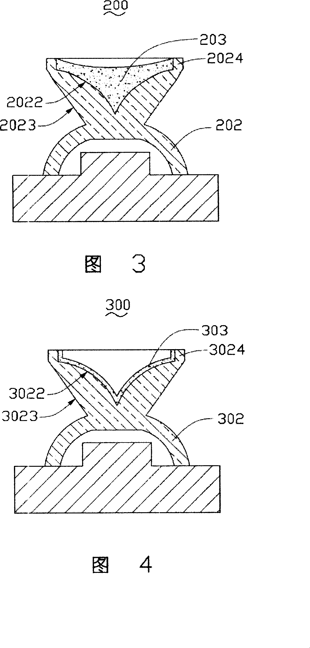
[0018] Please refer to FIG. 2 , which is a schematic cross-sectional view of a preferred embodiment 1 of the light emitting diode of the present invention. The light emitting diode 100 includes a semiconductor light emitting element 101 , a light guide prism 102 and an aluminum paste coating 103 . The light guide prism 102 includes a light incident surface 1021 opposite to the semiconductor light emitting element 101 , a top surface 1022 opposite to the light incident surface 1021 , and a light exit surface 1023 outside the light guide prism 102 and connected to the top surface 1022 . The aluminum paste paint coating 103 is formed on the top surface 1022, which includes a transparent resin substrate and a plurality of aluminum scales dispersed on the transparent resin substrate.

[0019] According to different ligh...


PUM


Abstract

This invention discloses a LED including a semiconductor light-emitting element and a light-conducting prism, in which, the prism includes a light-entry face opposite to the element, a top surface opposite to the light-entry face and a light-exit face outside of the prism, said LED also includes a coat of Al slurry containing a transparent resin backing and multiple Al squamas dispersed on the backing having the advantage of reducing light exit in a small angle to the vertical direction.

Description

technical field [0001] The invention relates to a light-emitting diode and a preparation method thereof, in particular to a side-light light-emitting diode and a preparation method thereof. Background technique [0002] Currently, the light emitting devices in the backlight module are generally cold cathode fluorescent lamps (Cold Cathode Fluorescent Lamp, CCFL) and light emitting diodes (Light Emitting Diode, LED). Among them, a light-emitting diode is a solid-state semiconductor light-emitting device, which uses the combination of two types of carriers (negatively charged electrons and positively charged holes) separated in the diode to generate light. Compared with cold-cathode fluorescent lamps, light-emitting diodes have the advantages of high color saturation, no mercury, long life, and adjustable color temperature through driving current. [0003] Please refer to FIG. 1 , which is a schematic diagram of a backlight module using an existing light-emitting diode. The ...

Claims


Application Information

Patent Timeline
Patent Type & Authority Applications(China)
IPC IPC(8): H01L33/00H01L33/58H01L33/60
CPCG02B19/0061G02B19/0028H01L33/58G02B17/0868H01L33/60
Inventor 章绍汉
Owner HONG FU JIN PRECISION IND (SHENZHEN) CO LTD
Learn More