A design method for limited impact response filter

A technology of impulse response and design method, which is applied in the direction of electrical components, digital technology network, impedance network, etc., can solve the problem of large resource overhead, and achieve the effect of simplifying the design process, reducing usage, and improving design efficiency

Inactive Publication Date: 2008-03-26
SHANDONG UNIV
View PDF0 Cites 0 Cited by
  • Summary
  • Abstract
  • Description
  • Claims
  • Application Information

AI Technical Summary

Problems solved by technology

[0003] Aiming at the problem of large resource overhead in existing FIR filter design, the present invention provides a method for designing a finite impulse response (FIR) filter with small resource overhead and low design cost

Method used


Image

  • A design method for limited impact response filter

Examples


Embodiment

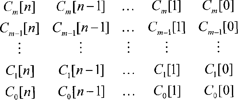
[0026] Taking a 16-order FIR filter as an example, the method of the present invention is specifically described. Expand all its coefficients in binary form to form a "coefficient array", as shown below:

[0027] 0010 1011 0011 1010

[0028] 1000 1000 0100 0110

[0029] 0001 0010 0000 0001

[0030] 0100 0100 1000 0000

[0031] 0010 0100 1100 0101

[0032] 1000 1001 0000 1000

[0033] 0001 0000 0001 0100

[0034] 0100 0010 0010 0011

[0035] 0001 0010 0000 1001

[0036] 0100 0100 0110 1010

[0037] 1000 1001 1000 0000

[0038] 0010 0000 0101 0100

[0039] 0100 1100 1010 0010

[0040] 0010 0110 0001 0001

[0041] 1001 0000 0101 0100

[0042] 0010 0001 1010 1000

[0043] Process according to the design method of the present invention below:

[0044] 1 produces a new collection

[0045] (1) For the first column from the left (0100010000100010) T , split into the following four new sub-columns according to the position of the item whose element value is 1: (0100000...


PUM


Abstract

This invention discloses a designing method for a limit impulse response filter, which expresses cofficients of a FIR filter in a binary system mode and displays it to a cofficnent array and then splits it to generate several new sub-arrays with a special rule, in which, each sub-array corresponds to a sub-shearch list, the output value of which is composed of corresponding bits of its input data directly, so a 1ut unit is not needed, finally, outputs of the sub-lists are accumulated to get output value of a total list.

Description

technical field [0001] The invention relates to a FIR (finite impulse response) filter design method based on FPGA (field programmable gate array) and distributed algorithm, belonging to the technical field of FIR filter. Background technique [0002] FIR filters play a very important role in scientific research and actual production. With the development of electronic design automation technology, it has become possible to use FPGA technology to design FIR filters. Due to its advantages of high integration and stable performance, this This technology is being promoted and applied more and more. At present, the design of FIR filter based on FPGA mainly adopts distributed algorithm. Since the look-up table technology is cited in this algorithm, it has a faster calculation speed than the traditional multiply-accumulate method, which satisfies the needs of actual high-speed calculation. But at the same time, this algorithm also consumes a lot of FPGA internal resources due to ...

Claims


Application Information

Patent Timeline
Patent Type & Authority Applications(China)
IPC IPC(8): H03H17/02
Inventor 袁东风王昆
Owner SHANDONG UNIV
Why Eureka
Try Eureka