Double-impeller multi-power full automatic washing machine
The technology of a fully automatic washing machine and double pulsator is applied to other washing machines, washing machines with containers, gear transmissions, etc., which can solve the problems of long washing time and other problems, and solve the problem of winding, improve washing efficiency and washing uniformity. Effect
- Summary
- Abstract
- Description
- Claims
- Application Information
AI Technical Summary
Problems solved by technology
Method used
Image
Examples
Embodiment 1
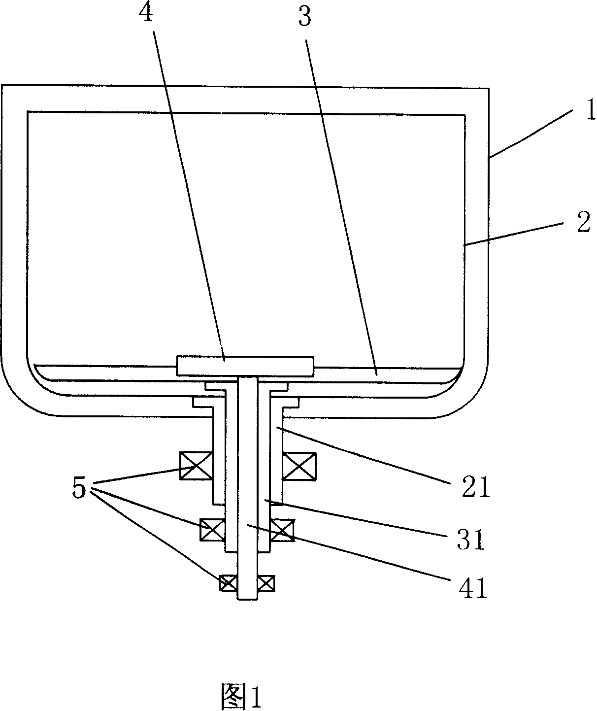
[0039] As shown in Figure 1, it is a schematic structural view of Embodiment 1 of the double-pulsator multi-power automatic washing machine of the present invention. It can be seen from the figure that a hollow inner barrel shaft 21 is fixed at the center of the bottom of the inner tub 2, and the large pulsator 3 The large wave wheel shaft 31 is also a hollow shaft, and is coaxially arranged in the inner barrel shaft 21; the small wave wheel shaft 41 of the small wave wheel 4 is coaxially arranged in the large wave wheel shaft 31; The inner barrel shaft 21, the large wave wheel shaft 31, and the small wave wheel shaft 41 are described.
[0040] When working, the computer board will control the three motors to rotate according to the preset speed and direction of rotation, so as to obtain the best washing effect. The large and small pulsators rotate coaxially and reversely during washing. It can be a powerful washing or rinsing that rotates in a single direction, or a standard ...
Embodiment 2
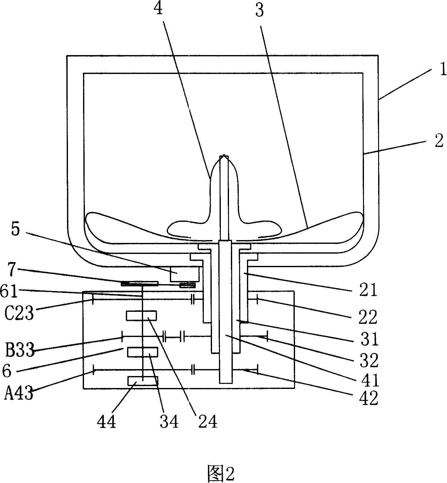
[0042] As shown in Figure 2, it is a schematic structural view of Embodiment 2 of the double-wave wheel multi-power automatic washing machine according to the present invention. The drive motor 5 described in this structure is fixed at the bottom of the outer tub 1, and is fixed at the bottom of the outer tub. A transmission clutch 6 is also provided, and a hollow inner barrel shaft 21 is fixed at the center of the bottom of the inner barrel 2. The big wave wheel shaft 31 of the big wave wheel 3 is also a hollow shaft, and is coaxially arranged in the inner barrel shaft 21. The small wave wheel 4 The pulsator shaft 41 coaxially arranged in the drive motor 5 described in the large pulsator shaft 31 is one, and is respectively connected and driven to the inner barrel shaft 21, the large pulsator shaft 31, and the small pulsator shaft 41 through the transmission clutch 6 fixed at the bottom of the outer tub.
[0043] The specific structure is that the inner barrel gear 22, the lar...
Embodiment 3
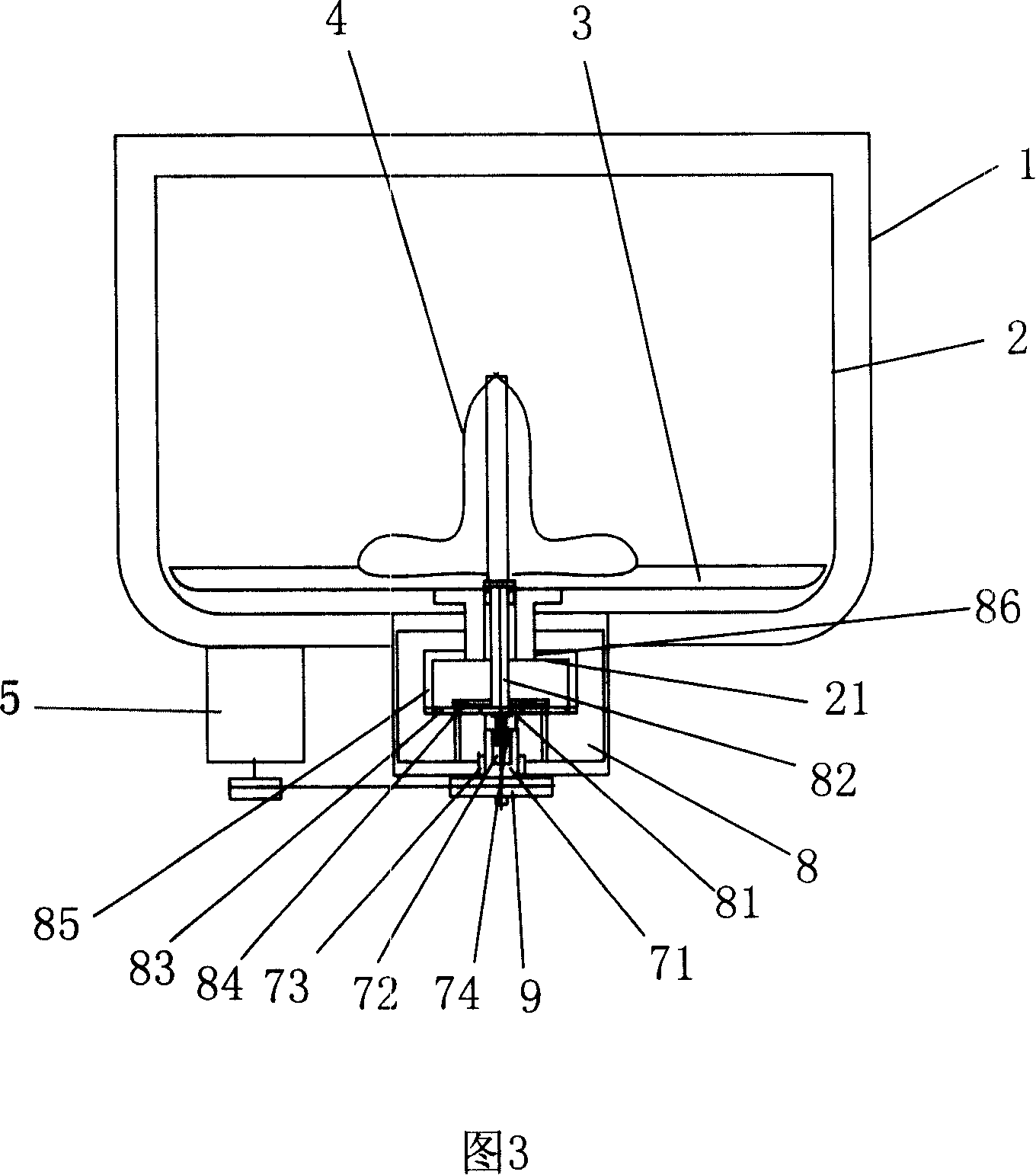
[0048] As shown in Figure 3, it is a structural schematic diagram of Embodiment 3 of the present invention. As can be seen from the figure, the transmission clutch includes a clutch and a gearbox 8, and one end of the input shaft 71 of the clutch has a central hole 72, and the other end is provided with a drive motor. The pulley 9; the outer circle and the inner hole at one end of the central hole are respectively provided with an outer circle one-way bearing 73 and an inner hole one-way bearing 74, and the outer circle one-way bearing 73 and the inner hole one-way bearing The rotation direction of 74 is opposite, the outer circle one-way bearing 73 is fixedly connected with the gearbox 8, and the gearbox 8 is fixedly connected with the outer tub 1; the gearbox 8 is a planetary gear train gearbox, so One end of the wheel shaft 82 of the sun gear 81 of the planetary gear system is used as an input shaft to connect the inner hole one-way bearing 74, and the other end of the wheel...
PUM
 Abstract
Description
Claims
Application Information
 - R&D
- Intellectual Property
- Life Sciences
- Materials
- Tech Scout
- Unparalleled Data Quality
- Higher Quality Content
- 60% Fewer Hallucinations
Browse by: Latest US Patents, China's latest patents, Technical Efficacy Thesaurus, Application Domain, Technology Topic, Popular Technical Reports.
© 2025 PatSnap. All rights reserved.Legal|Privacy policy|Modern Slavery Act Transparency Statement|Sitemap|About US| Contact US: help@patsnap.com


