
Dust collecting mechanism

一种空气泵、集尘的技术,应用在泵、用于弹性流体的泵送装置的部件、泵元件等方向,能够解决泵功能降低、隔膜性能降低、寿命降低等问题,达到防止沙尘的侵入、组装作业简单、紧凑构造的效果

Inactive Publication Date: 2008-04-02
TECHNO TAKATSUKI
View PDF1 Cites 12 Cited by
  • Summary
  • Abstract
  • Description
  • Claims
  • Application Information

AI Technical Summary

Problems solved by technology

[0006] In addition, in the electromagnetic vibration type pump of piston type and diaphragm type, the life of the pump is affected by the wear and damage of the piston, the damage of the diaphragm, the damage of the valve, and the performance reduction caused by the damage of the pump and the reduction of the function of the pump.
Dust, foreign matter (for example, hard-pointed minute foreign matter) contained in the fluid flowing in from the atmosphere or outside the pump will cause significant damage or damage to the piston and diaphragm as functional parts, or damage or damage to the valve, which will shorten the service life. main reason

Method used


Image

  • Dust collecting mechanism
  • Dust collecting mechanism
  • Dust collecting mechanism

Examples


Embodiment 1

[0093] As shown in FIG. 8 , a container composed of five small chambers divided by four partition walls 4 and communicated through vent holes 4 a arranged differently from each other was manufactured. In FIG. 8 , a member denoted by reference numeral 8 is a deflection plate, and the deflection plate 8 is inclined by an angle θ (θ=25 degrees) with respect to the partition wall 4 so as to approach the vent hole 4 a.

[0094] Like this, the result of making the air mixed with dust flow in from the inlet 6 is clear: (1) in the small chamber with the deflector 8, the generation of the vortex is less, (2) the dust crosses the deflector 8, and (3) the dust It is easy to stay in the small chamber where the outlet 7 is provided, and there is a possibility that the dust may flow out from the outlet 7 to the pump.

Embodiment 2

[0096] As shown in FIG. 9 , a container composed of five small chambers divided by four partition walls 4 and communicated through vent holes 4 a arranged differently from each other was manufactured. In FIG. 9 , the member denoted by reference numeral 8 is a deflecting plate, and both the upper deflecting plate 8 a and the lower deflecting plate 8 b are inclined at an angle θ (θ=45 degrees) relative to the partition wall 4 so as to be away from the air vent.

[0097] As a result of making the air mixed with dust flow in through the inlet 6 in this way, in FIG. 9, the polarizing plate 8b is provided at the lower part, but it may be provided at the upper and lower parts respectively. It was found that the blow pile 9 was generated on the lower side of the deflector plate 8b.


PUM


Abstract

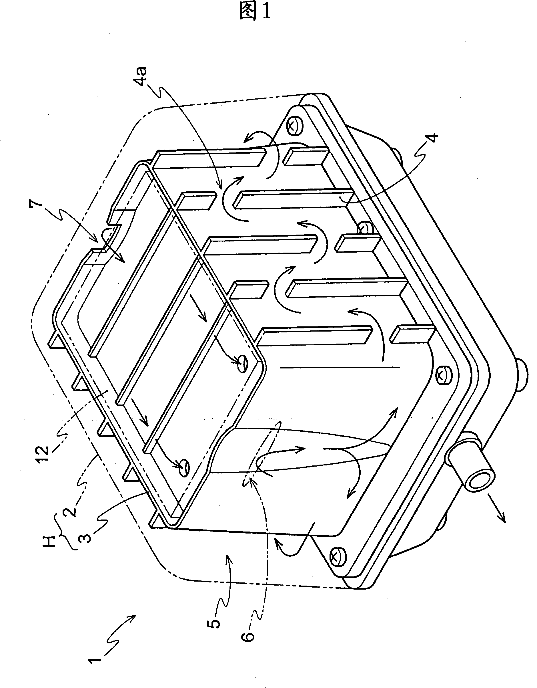
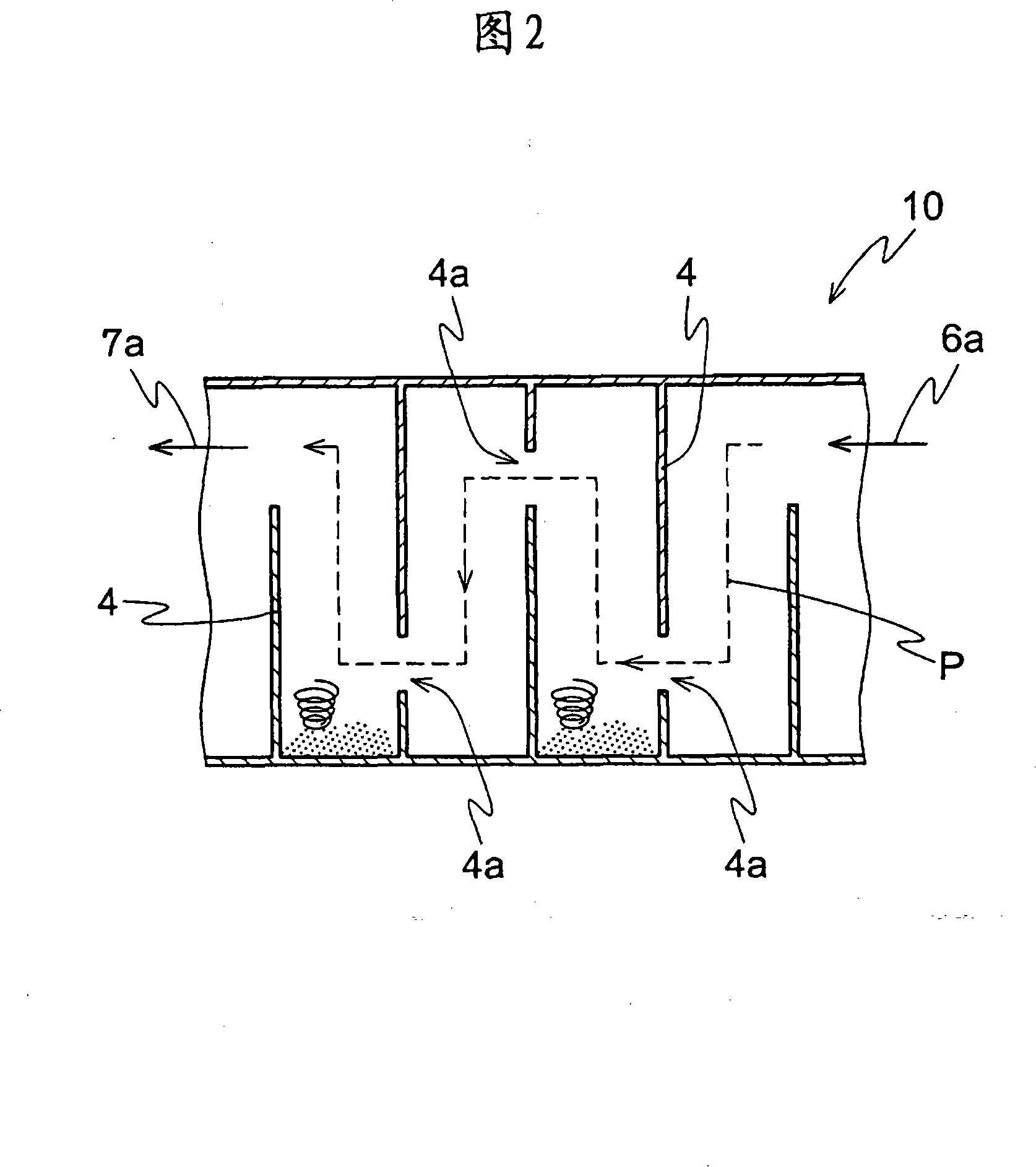
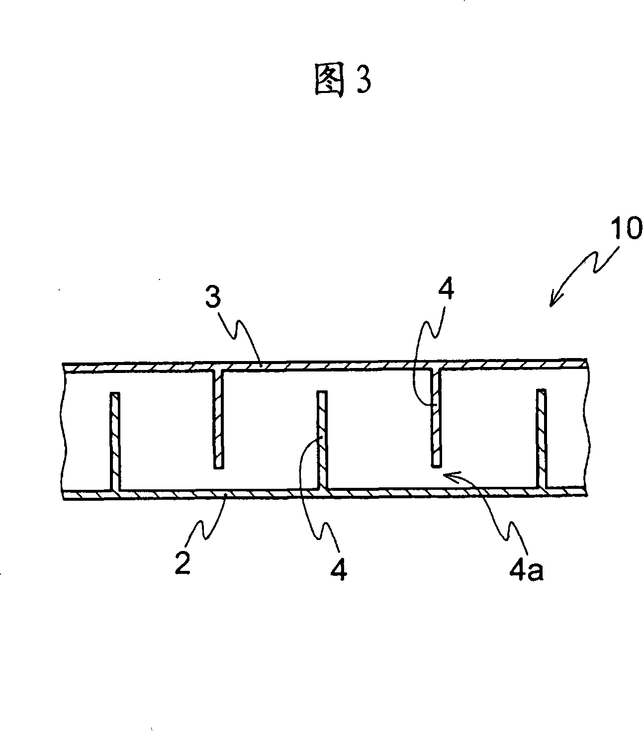
An object of the present invention is to provide a dust collecting mechanism for an air pump, in particular, an electromagnetic vibrational pump having a compact structure, capable of realizing the efficiency of dust collecting ability and simple in assembly work. The present invention is characterized in that the inlet and outlet of fluid are provided at a barrier chamber provided in at least one portion of a housing, a plurality of cross walls at which 1 or 2 or more of vent holes are provided are arranged, and at least the position of the vent hole of the adjacent cross wall is different among a plurality of the cross walls.

Description

technical field [0001] The invention relates to a dust collecting mechanism of an air pump. More specifically, it relates to a dust collecting mechanism of an electromagnetic vibrating air pump mainly for supplying oxygen to a domestic purification tank, a fish tank, and the like. However, the dust collecting mechanism of the present invention is not limited to the air pump (electromagnetic vibration type air pump) applied to this specific type, and can be applied to general air pumps. Background technique [0002] Conventionally, as such a pump, a diaphragm pump as shown in FIGS. 17-18 is disclosed (refer to Patent Document 1). In this way, the diaphragm pump of FIG. 18 consists of an electromagnet disposed opposite to the frame in the pump casing 200, a vibrator with a permanent magnet, diaphragms connected to both ends of the vibrator, and respectively fixed to both ends of the frame. side pump casing. In addition, a dust collection unit 201 is provided on the upper po...

Claims


Application Information

Patent Timeline
Patent Type & Authority Applications(China)
IPC IPC(8): F04B39/16
CPCB01D45/06B01D45/08F04B45/043F04B39/16F04B45/047F04D29/70
Inventor 川崎望
Owner TECHNO TAKATSUKI
Learn More