Supercharge Your Innovation With Domain-Expert AI Agents!

Drive circuit, electrooptical device and electronic equipment

A technology for drive circuits and optoelectronic devices, applied in the fields of drive circuits, optoelectronic devices, and electronic equipment, can solve the problems of increased charge and discharge charge, dependence, and weakening of the effect of low power consumption, so as to reduce current consumption and reduce chip size , to achieve the effect of power consumption

Inactive Publication Date: 2008-04-02
SEIKO EPSON CORP
View PDF2 Cites 8 Cited by
  • Summary
  • Abstract
  • Description
  • Claims
  • Application Information

AI Technical Summary

Problems solved by technology

[0009] However, the technologies disclosed in Patent Document 1 and Patent Document 2 have a problem that the reduction effect of power consumption depends on a given voltage on the source line.
Therefore, there are cases where the reduction effect of the amount of electric charge that charges and discharges the counter electrode whose polarity is reversed is less than ideal
In addition, in the technique disclosed in Patent Document 1, there is a problem in that the two electrodes interposing the liquid crystal are short-circuited depending on the relationship between the voltage given on the source line and the polarity of the counter electrode voltage, thereby The amount of charge that should be charged and discharged will increase instead, and the effect of low power consumption will be weakene

Method used


Image

  • Drive circuit, electrooptical device and electronic equipment
  • Drive circuit, electrooptical device and electronic equipment
  • Drive circuit, electrooptical device and electronic equipment

Examples


Embodiment Construction

[0059] Preferred embodiments of the present invention will be described in detail with reference to the following drawings. In addition, the Examples described below do not unduly limit the content of the present invention described in the claims. Not all structures described below are necessarily essential components of the present invention.

[0060] 1. Liquid crystal device

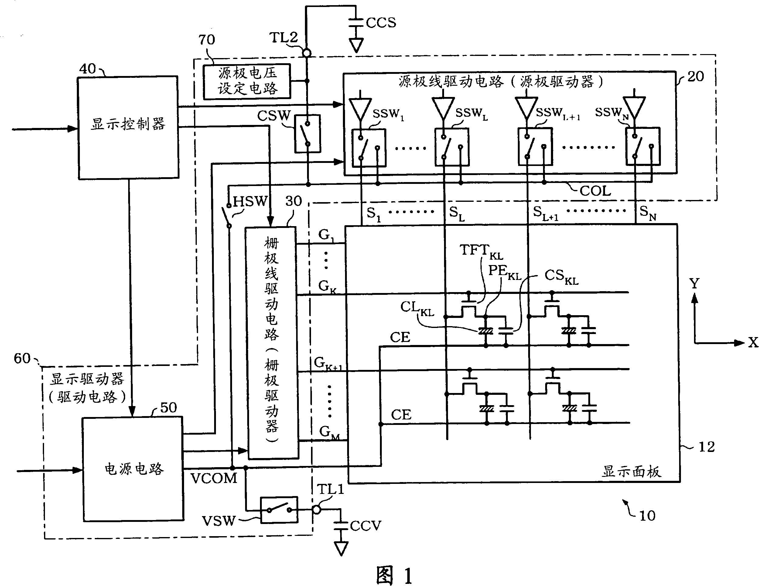
[0061] FIG. 1 is an example of a block diagram of a liquid crystal device of this embodiment.

[0062] A liquid crystal device 10 (a liquid crystal display device. A display device in a broad sense) includes a display panel 12 (a LCD (Liquid Crystal Display) panel in a narrow sense), a source line driver circuit 20 (a source driver in a narrow sense), a gate line driver circuit 30 (a gate driver in a narrow sense), a display controller 40 , a power supply circuit 50 , and a source voltage setting circuit (a voltage setting circuit in a broad sense) 70 . In addition, the liquid crystal device 10 does...


PUM


Abstract

The invention discloses a drive circuit which realizes the high speed, low-power consumption and low cost, an electrooptical device and an electrical device. The drive circuit for driving the source line of the electrooptical device comprises: a first and a second source short circuit, each of which is used for making respective source line of the first and the second source lines and the preset source short circuit node short circuit; a source charge storage short circuit for making the source charge storage node connected with one end of the source capacitor and the source short circuit node short circuit; a voltage setting circuit for providing the preset voltage to the source charge storage node; a node short circuit for making the opposite electrode voltage output node and the source short circuit node short circuit, wherein, the opposite electrode voltage output node is additionally provided with the voltage output by the opposite electrodes and the opposite electrodes are configured with the pixel electrode of the electrooptical device in a partition of the electrooptical element.

Description

technical field [0001] The present invention relates to drive circuits, optoelectronic devices and electronic equipment. Background technique [0002] In recent years, as a liquid crystal display (Liquid Crystal Display: LCD) panel (a display panel in a broad sense; an optoelectronic device in a broader sense) mounted on electronic equipment such as a mobile phone, there are known simple matrix LCD panels and the use of An active-matrix LCD panel using switching elements such as thin film transistors (Thin Film Transistor: hereinafter referred to as TFT). [0003] The simple matrix method is easier to achieve lower power consumption than the active matrix method, but it is difficult to realize multi-color and moving image display. On the other hand, the active matrix method is suitable for multi-color and moving image display, but it is difficult to achieve low power consumption. [0004] A simple matrix type LCD panel or an active matrix type LCD panel is driven so that t...

Claims


Application Information

Patent Timeline
IPC IPC(8): G09G3/36G09G3/20G02F1/133
Inventor 上条治雄西村元章野村猛
Owner SEIKO EPSON CORP
Features
  • R&D
  • Intellectual Property
  • Life Sciences
  • Materials
  • Tech Scout
  • Unparalleled Data Quality
  • Higher Quality Content
  • 60% Fewer Hallucinations
Learn More