Rotating anode x-ray tube assembly

A technology of rotating anodes and ray tubes, which is applied to X-ray tubes, X-ray tube parts, X-ray tube electrodes, etc., and can solve problems such as shortening the life of the collector ring mechanism

Inactive Publication Date: 2008-04-02
KK TOSHIBA +1
View PDF4 Cites 22 Cited by
  • Summary
  • Abstract
  • Description
  • Claims
  • Application Information

AI Technical Summary

Problems solved by technology

In this case, the life of the slip ring mechanism is shortened due to the wear of the sliding part

Method used


Image

  • Rotating anode x-ray tube assembly
  • Rotating anode x-ray tube assembly
  • Rotating anode x-ray tube assembly

Examples


Embodiment Construction

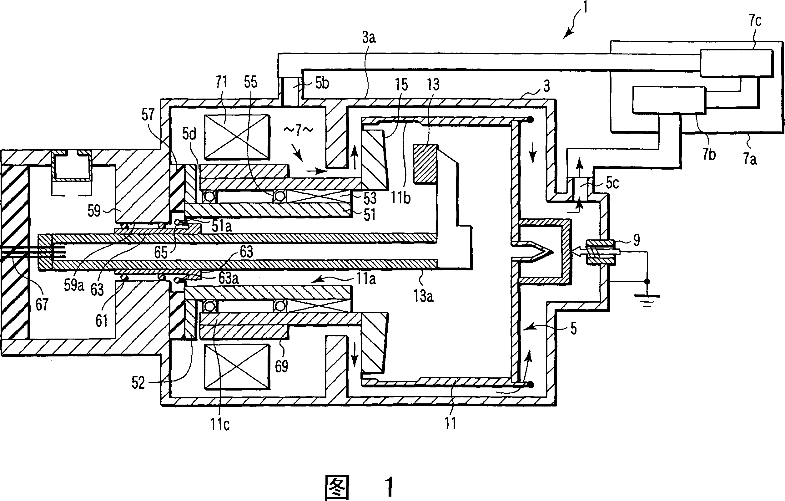
[0052] Hereinafter, embodiments of the present invention will be described in detail with reference to the accompanying drawings.

[0053] As shown in FIG. 1 , the X-ray tube assembly 1 is configured, for example, as an X-ray imaging diagnostic device and a non-destructive tester. The X-ray tube assembly 1 emits X-rays toward a target, ie, a test target. The X-ray tube assembly 1 has a housing 3 and an X-ray tube body (rotating anode X-ray tube) 5 . The X-ray tube body 5 is accommodated in the housing 3, and emits X-rays with a predetermined intensity in a predetermined direction.

[0054] The X-ray tube body 5 is accommodated at a predetermined position of the housing 3 by means of a coolant 7 . The coolant 7 is mainly composed of, for example, water, and is a non-oil cooling liquid (water-based cooling medium) having an electrical conductivity smaller than a predetermined value. A cooling medium having a conductivity of less than 1 mS / m is used as the coolant 7 to ensure ...


PUM


Abstract

There is disclosed a rotating anode X-ray tube assembly comprising a vacuum envelope (11) integrated with an anode target (15), a housing (3) receiving at least the vacuum envelope, and rotatably holding it, a circulation path circulating a cooling medium (7) closed to at least the anode target of the vacuum envelope, a cathode (13) received and arranged in the vacuum envelope, a cathode support member (13a) supporting the cathode, a bearing mechanism and a vacuum sealing mechanism interposed between the vacuum envelope, and the housing or a stationary member directly or indirectly fixed to the housing, and a driver unit for rotating the vacuum envelope.

Description

technical field [0001] This invention relates to rotating anode X-ray tube assemblies. In particular, the present invention relates to a structure for improving the heat dissipation performance of an anode. Background technique [0002] Conventional rotating anode X-ray tube assemblies that improve the heat dissipation properties of the anode fall broadly into the following two types: [0003] (1) Type 1: The rotating anode X-ray tube assembly includes a rotating anode X-ray tube and a casing. A rotating anode ray tube is configured to receive a rotatably supported anode target in a vacuum envelope. A housing is provided to receive a rotating anode X-ray tube. In order to remove heat from the anode target, a circulation path for circulating a cooling medium in the anode target is provided (for example, see Japanese Patent Application KOKOKU Publication No. H5-27205 and Japanese Patent Application Publication No. 2006-54181). [0004] The heat from the anode target is con...

Claims


Application Information

Patent Timeline
Patent Type & Authority Applications(China)
IPC IPC(8): H01J35/00H01J35/10
Inventor 阿武秀郎
Owner KK TOSHIBA
Why Eureka
Try Eureka