Repair joint of photoelectric composite sea cable

A photoelectric composite and optical cable joint technology, which is applied in the direction of optical fiber/cable installation, clamping/spring connection, fiber mechanical structure, etc., can solve the problems of inability to connect submarine cables, etc., and achieve simple structure, reliable operation, and simple installation and operation procedures Effect

Active Publication Date: 2008-04-09
宁波东方电缆股份有限公司
View PDF0 Cites 4 Cited by
  • Summary
  • Abstract
  • Description
  • Claims
  • Application Information

AI Technical Summary

Problems solved by technology

Submarine optical cables or submarine power cables often fail due to various reasons during the long-term use of the submarine. In order to ensure the normal operation of the submarine cable, it is necessary to use joints to connect the submarine cable at the fault point. At present, the connection of the submarine cable often uses a soft But the soft joint can only be spliced ​​with special tools at the production site, and it cannot be spliced ​​at sea

Method used


Image

  • Repair joint of photoelectric composite sea cable
  • Repair joint of photoelectric composite sea cable
  • Repair joint of photoelectric composite sea cable

Examples


Embodiment 1

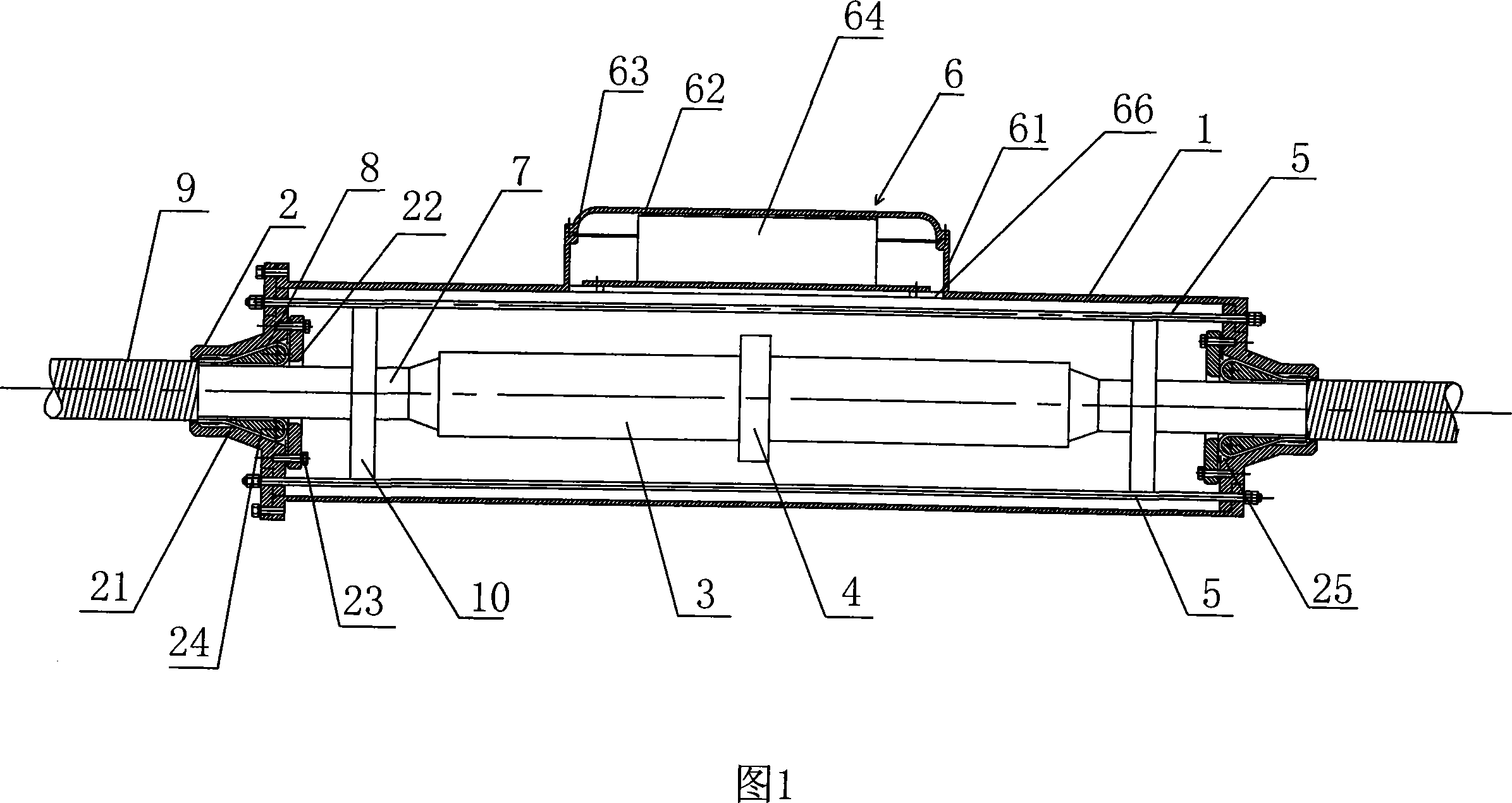
[0018] Embodiment 1: As shown in Figure 1, a repair joint of a photoelectric composite submarine cable, which includes a cylinder body 1 and cover plates 2 arranged at both ends of the cylinder body 1, the cylinder body 1 and the cover plate 2 cooperate to form an integral body, and the submarine cable 7. The through cover plate 2 is joined in the cylinder body 1. In this embodiment, the cylinder body 1 is made of hard organic material, which can be hard PVC or epoxy glass fiber reinforced plastic, and the surface is coated with a layer of epoxy paint for mechanical protection. effect. The cover plate 2 is provided with a sealing fixing part, and a set of conductive pull rods 5 is arranged between the sealing fixing part and the cylinder body 1. The sealing fixing part is electrically connected with the conductive pull rods 5. The setting of the conductive pull rods 5 not only ensures the armored The electrical connection between the steel wires effectively tightens the cylind...

Embodiment 2

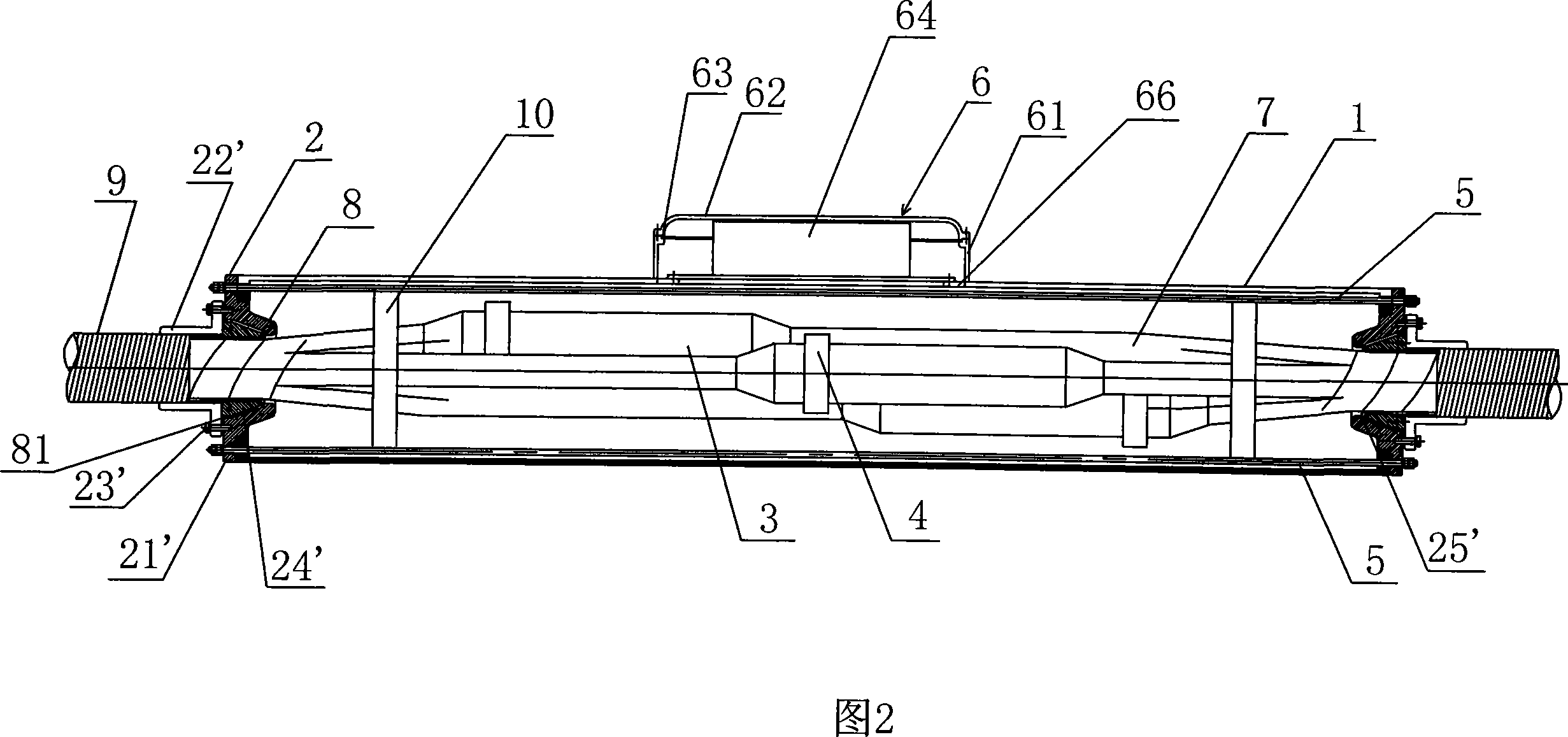
[0024] Embodiment 2: As shown in Figure 2, its structure is basically the same as that of Embodiment 1, the difference is that in this embodiment, the sealing fixture adopts another structure, which includes a tapered hole 25 located inside the cylinder body 1 'The conical base 21' and the L-shaped pressure plate 22' fixedly connected with the conical base 21' can be connected by screws 23'. A tapered sleeve 24' is arranged between the L-shaped pressure plate 22' and the tapered hole 25', and the armored steel wire 8 of the submarine cable 7 is wrapped outside the tapered sleeve 24', and the armored steel wire 8 and the tapered sleeve 24' are connected to the tapered hole 25. 'cooperate with each other, the free end 81 of the armored steel wire 8 and the L-shaped pressing plate 22' conflict with each other, one end of the L-shaped pressing plate 22' is connected with the sheath 9 of the submarine cable 7, the conical base 21', the L-shaped pressing plate 22' and the conical Th...


PUM


Abstract

The invention discloses a photoelectric composite submarine cable repair joint, which comprises a cylinder and cover boards arranged on two ends of the cylinder, the submarine cable penetrates the cover boards and jointed in the cylinder, the cover board is provided with an airproof fixation piece, a set of electricity conductive drawbars electrically connected with the airproof fixation piece is arranged between the airproof fixation piece and the cylinder, the submarine cable in the cylinder is provided with two mutual assorted inner cylinders, a double components resin is arranged in the two inner cylinder, the outer surface of the cylinder is provided with an optic cable joint package, the optic cable is connected with the optic cable joint package through the cylinder, a double components resin is arranged in the optic cable joint package, the invention has the advantages that: due to the setting of the airproof fixation piece, two fault ends of the submarine cable is fixed, the cutting of the submarine cable in the joint position under an outside force action is avoided; the setting of the electricity conductive drawbars ensures the electric communication between the jacket steel wire of the two submarine cable fault ends; due to the setting of the optic cable joint package, the optic cable is connected with the optic cable joint package through the cylinder and ensures the electric communication of the optic cable; the setting of the double components resin plays the role of anti-corrosion, waterproof, and airproof.

Description

technical field [0001] The invention relates to a joint, in particular to a repair joint of a photoelectric composite submarine cable. Background technique [0002] With the rapid development of economy and construction, many offshore islands and marine facilities such as offshore oil and natural gas work platforms have demands for various resources such as electricity, communications, fresh water, oil, and gas, and various seabeds have to be deployed separately. A large number of pipelines such as optical cables and submarine power cables. Submarine optical cables or submarine power cables often fail due to various reasons during the long-term use of the submarine. In order to ensure the normal operation of the submarine cable, it is necessary to use joints to connect the submarine cable. At present, the connection of submarine cables often uses a soft However, the soft joint can only be connected with special tools at the production site, and the submarine cable connectio...

Claims


Application Information

Patent Timeline
Patent Type & Authority Applications(China)
IPC IPC(8): G02B6/44G02B6/50H01R4/50
Inventor 王逢春叶信宏
Owner 宁波东方电缆股份有限公司
Why Eureka
Try Eureka