Cleaning blade for use in image-forming apparatus

A technology for cleaning a blade and an imaging device, which is applied in the direction of an electric recording process applying a charge pattern, equipment and instruments for an electric recording process applying a charge pattern, etc. Abrasion resistance, inability of cleaning blade to have sufficient toner removal function, etc.

Inactive Publication Date: 2010-06-02
SUMITOMO RUBBER IND LTD
View PDF10 Cites 0 Cited by
  • Summary
  • Abstract
  • Description
  • Claims
  • Application Information

AI Technical Summary

Problems solved by technology

Therefore, the cleaning blade cannot have sufficient toner removal function
[0016] In addition, since the side of these cleaning blades in contact with the photosensitive drum is made of a material with relatively high hardness, the cleaning blades are brittle and have insufficient abrasion resistance
Therefore, the cleaning blade cannot provide sufficient cleaning effect for a long time

Method used

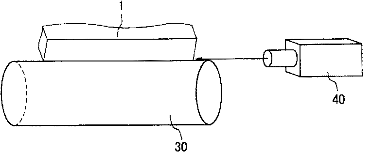
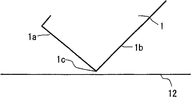
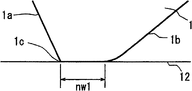

Image

  • Cleaning blade for use in image-forming apparatus
  • Cleaning blade for use in image-forming apparatus
  • Cleaning blade for use in image-forming apparatus

Examples


preparation example Construction

[0221] The preparation of the thermoplastic elastic composition used among the present invention is as follows:

[0222] First, the rubber component (1) and The filler (2) is kneaded at 80-120° C. for 5-6 minutes. If the kneading temperature is lower than 80° C. and the kneading time is less than 5 minutes, the rubber component (1) is insufficiently plasticized, and the mixture cannot be sufficiently kneaded. If the kneading temperature is higher than 120°C and the kneading time is longer than 6 minutes, the rubber component (1) may decompose.

[0223] After adding the crosslinking agent (3) to the prepared mixture, it is kneaded at 80 to 90° C. for 5 to 6 minutes using the above-mentioned kneading device. If the kneading temperature is lower than 80° C. and the kneading time is less than 5 minutes, plasticization and kneading of the mixture are insufficient. If the kneading temperature is higher than 90°C and the kneading time is longer than 6 minutes, the crosslinking age...

Embodiment 13、14

[0319] Commercial urethane rubber sheets (commercial products 1 and 2) were used as the base layer and the edge layer.

[0320] The measurement results are shown in Table 4.

[0321]

[0322]

[0323] Table 4-2

[0324]

[0325] The units of the respective amounts of the rubber component (1), filler (2) and crosslinking agent (3) shown in Table 3 are parts by mass. The following products were used for the components shown in Table 3:

[0326] H-NBR (Hydrogenated Nitrile Butadiene Rubber): H-NBR was used as the base polymer, and "Zetpol 2010H" was used, purchased from Zeon Corporation (bonded acrylonitrile content: 36%, Mooney viscosity: 145)

[0327] ZDMA-containing H-NBR (finely dispersed zinc methacrylate in H-NBR as base polymer of rubber component (1): "Zeoforte ZSC 2195H" from Zeon Corporation (zinc methacrylate content : 50 parts by mass)

[0328] · Polyurethane rubber 1: Commercial polyurethane rubber sheet

[0329] · Polyurethane rubber 2: Commercial poly...


PUM

PropertyMeasurementUnit
tensile strengthaaaaaaaaaa
thicknessaaaaaaaaaa
lengthaaaaaaaaaa

Abstract

A cleaning blade (20) which is brought into contact with a peripheral surface of a photoreceptor drum (12) of an image-forming apparatus to remove toner which remains on the peripheral surface of thephotoreceptor drum (12). In a dynamic state in which the cleaning blade (20) contacts the photoreceptor drum (12) with a load of 2 to 60N and a face pressure of 1.3 to 66.7 MPa being applied thereto when the photoreceptor drum (20) is rotating, the cleaning blade (20) contacts the peripheral surface of the photoreceptor drum (12) in a contact width (nip width) of 3 to 10[mu]m. The cleaning blade (20) has a two-layer construction composed of a matrix layer (20-1) and an edge layer (20-2).

Description

technical field [0001] The present invention relates to a cleaning blade for an image forming device, and more particularly, to a cleaning blade that improves removal of residual The ability of the toner on the surface of the photosensitive drum. Background technique [0002] In an electrostatic copier using plain paper as recording paper, the copying operation proceeds as follows: electrostatic charge is applied to the surface of a photosensitive drum by discharge, an image is exposed to the photosensitive drum to form an electrostatic latent image thereon, and colors having opposite polarities Toner is adsorbed onto the electrostatic latent image to develop the electrostatic latent image, the toner image is transferred to recording paper, and the recording paper to which the toner image has been transferred is heated under pressure to fix the toner on the recording paper. Therefore, in order to continuously copy the image of the original document onto a plurality of sheet...

Claims


Application Information

Patent Timeline
Patent Type & Authority Patents(China)
IPC IPC(8): G03G21/00C08L9/02C08L7/00C08L47/00C08L23/22C08L11/00C08L33/00C08L75/04C08K5/09C08J5/18
CPCG03G21/0011G03G21/0017G03G2221/0005G03G15/08G03G21/00
Inventor 杉本睦树
Owner SUMITOMO RUBBER IND LTD
Why Eureka
Try Eureka