Bionic anklebone

A technology of ankle joints and joint bearings, applied in the field of bionic ankle joints, can solve the problems of high energy consumption of active control and inflexible passive control, etc., and achieve the effect of reducing energy loss, compact structure and flexible movement

Inactive Publication Date: 2008-04-16
TSINGHUA UNIV
View PDF0 Cites 24 Cited by
  • Summary
  • Abstract
  • Description
  • Claims
  • Application Information

AI Technical Summary

Problems solved by technology

In addition, the robot ankle joint generally adopts active or passive control, ac

Method used


Image

  • Bionic anklebone
  • Bionic anklebone
  • Bionic anklebone

Examples


Embodiment Construction

[0014] Further illustrate the present invention below in conjunction with accompanying drawing.

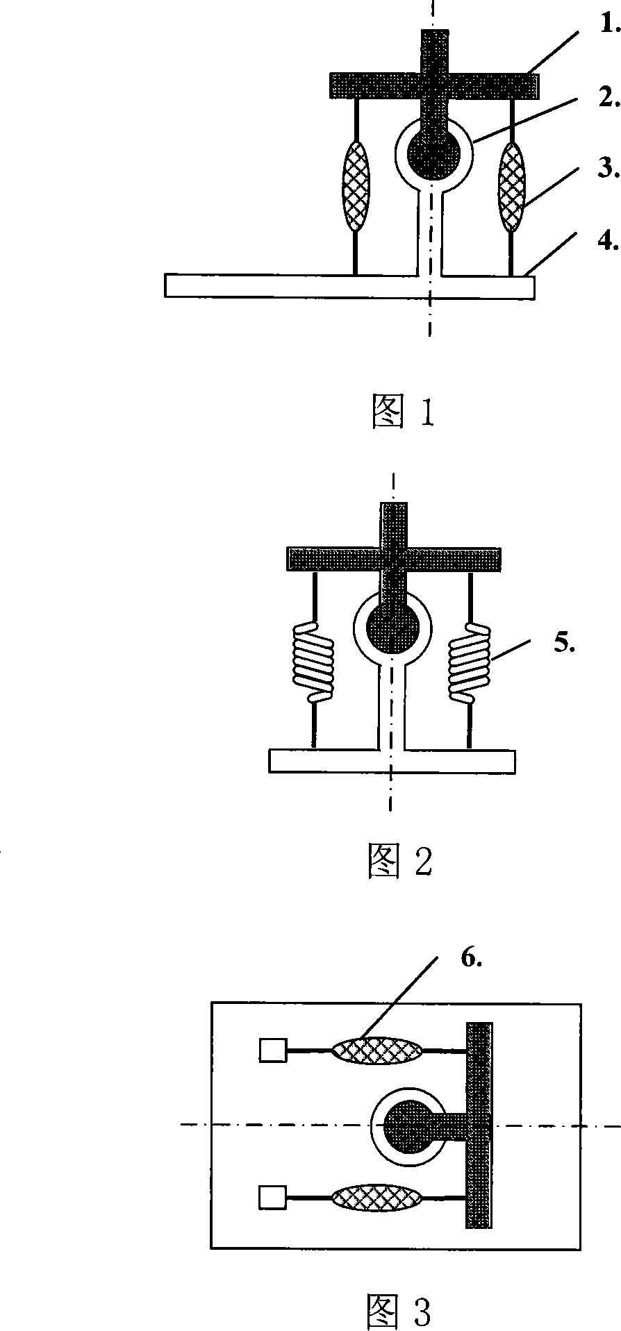
[0015] The ankle joint adopts the joint bearing 2, and the lifting and straightening motion of the ankle joint and the rotation motion around the axis of the calf are respectively controlled by a pair of pneumatic muscles. The lateral swing of the ankle joint is controlled by a pair of springs.

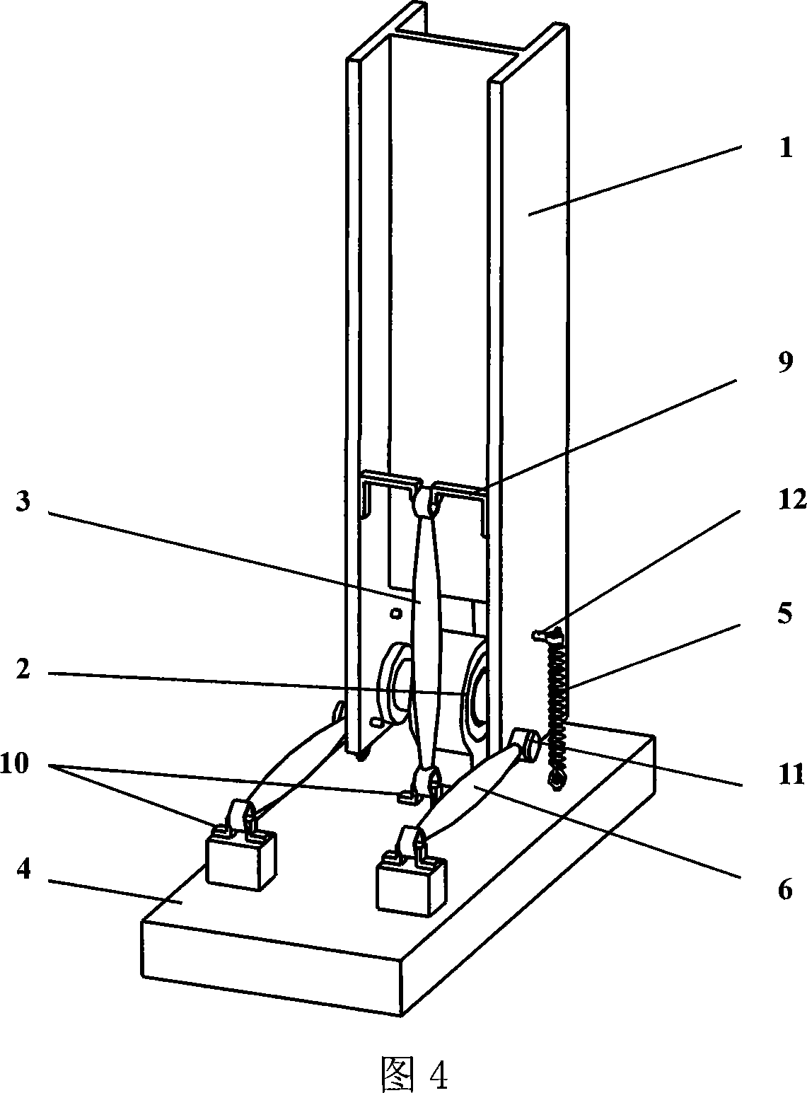
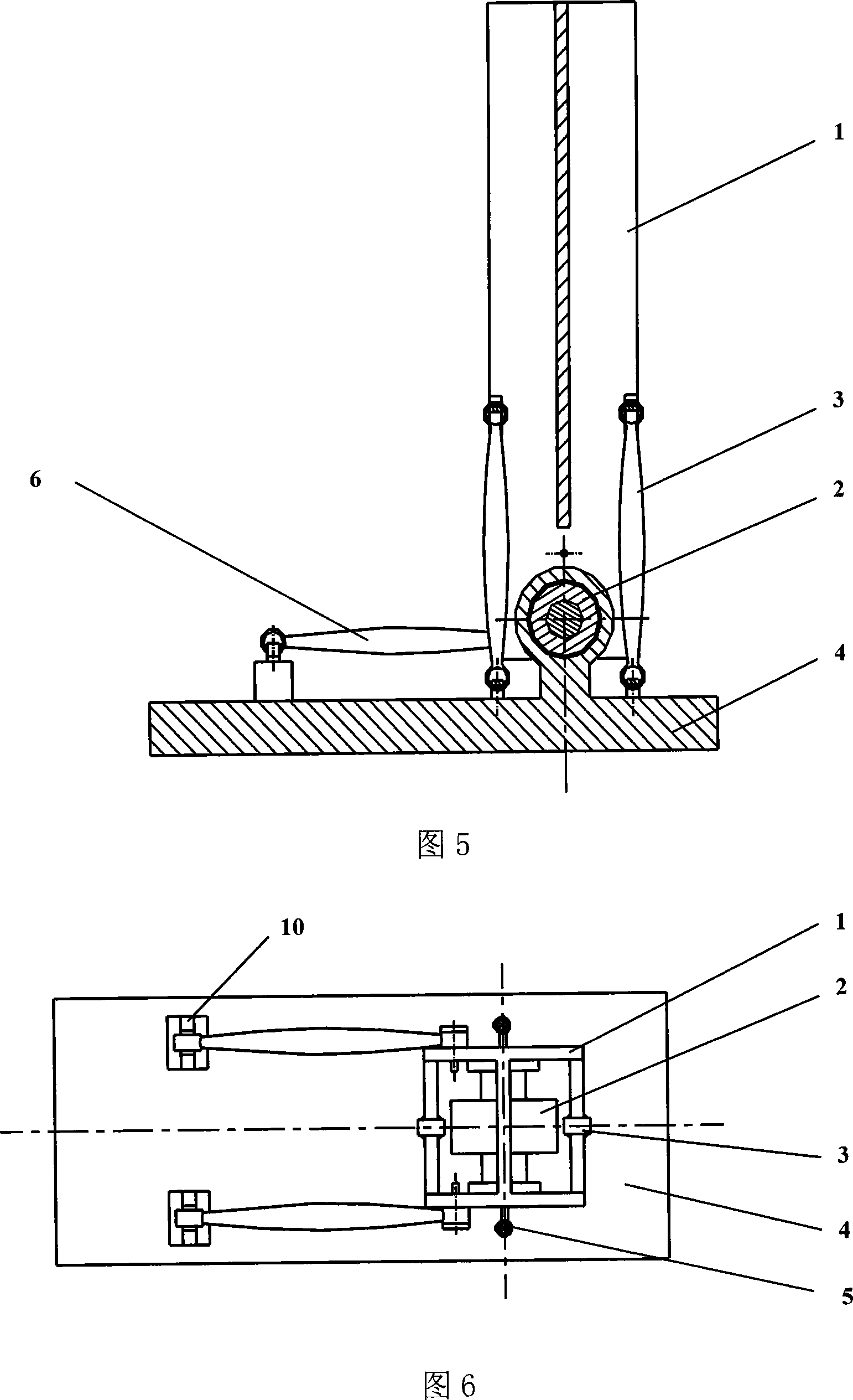
[0016] As shown in FIG. 1 and FIG. 4 , the bionic ankle joint includes a lower leg 1 , a centripetal joint bearing 2 , a first pneumatic muscle 3 , a spring 5 , a second pneumatic muscle 6 and a foot 4 . The inner ring of the centripetal joint bearing 2 is connected with the lower leg 1, the outer ring of the bearing is connected with the foot 4, and the outer ring rotates relative to the inner ring, driving the foot 4 to rotate relative to the lower leg 1. The specific connection methods are shown in Fig. 4, Fig. 5, Fig. 6 and Fig. 7. The lower leg 1 adopts an I-shaped plate, the outer ...


PUM


Abstract

The invention relates to a bionic ankle joint. The ankle joint uses joint bearing. The bearing inner ring is connected with the calf and the outer ring is connected with the foot. The outer ring revolves the inner ring. The foot of the robot is driven to move relative to the calf. The uplifting and unbending motion of ankle joint and the rotary motion along the axis line of the calf are respectively controlled by a pair of springs. One end of the spring is connected with the calf and the other end is connected with the foot. When the robot dumps towards the sideways, the equilibrium position is recovered under the function of spring. The invention can realize flexible motion of ankle joint with homocentric triaxiality with compact structure. The energy loss can be reduced using the mode of combining the pneumatic muscle active control and spring passive control and the effect of buffering can be obtained.

Description

technical field [0001] The invention relates to a bionic ankle joint, belonging to the technical field of robots. Background technique [0002] Robotic ankle joints generally adopt the form of multiple degrees of freedom in series, but the disadvantage is that the structure is not compact. Although the structure of the parallel ankle joint is relatively compact, the control is not simple and intuitive enough. Therefore, there is an urgent need for a robot ankle joint with compact structure and simple control. In addition, the robot ankle joint generally adopts active or passive control, active control consumes a lot of energy, and passive control is not flexible enough. If active and passive joint control can be adopted, better results will be achieved. Contents of the invention [0003] The object of the present invention is to propose a bionic ankle joint with compact structure and simple control in view of the deficiencies in the prior art. The ankle joint adopts ac...

Claims


Application Information

Patent Timeline
IPC IPC(8): B25J17/00
Inventor 陈恳王健美付成龙黄元林冯涛
Owner TSINGHUA UNIV
Why Eureka
Try Eureka