Power system of hybrid fuel cell bus and control method thereof

A power system, fuel cell technology, applied in battery/fuel cell control device, fuel cell, transportation fuel cell technology, etc.

Active Publication Date: 2008-04-16
HYUNDAI MOTOR CO LTD
View PDF1 Cites 34 Cited by
  • Summary
  • Abstract
  • Description
  • Claims
  • Application Information

AI Technical Summary

Problems solved by technology

[0011] Therefore, in order to develop a hybrid fuel cell bus, there is a problem of redesigning various electric parts and fuel cell systems

Method used


Image

  • Power system of hybrid fuel cell bus and control method thereof
  • Power system of hybrid fuel cell bus and control method thereof
  • Power system of hybrid fuel cell bus and control method thereof

Examples


Embodiment Construction

[0044] Exemplary embodiments of the present invention will be described in detail below with reference to the accompanying drawings.

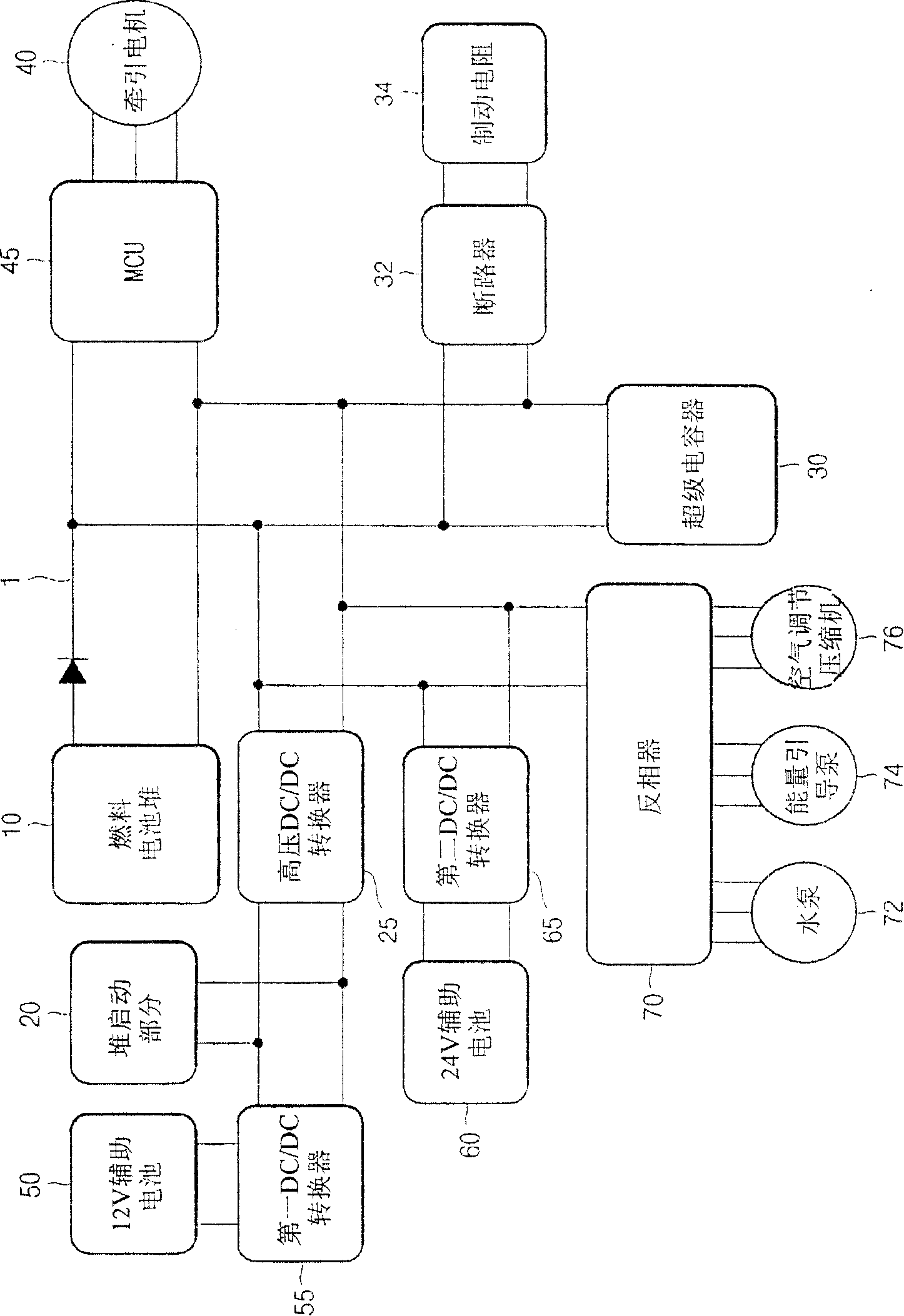
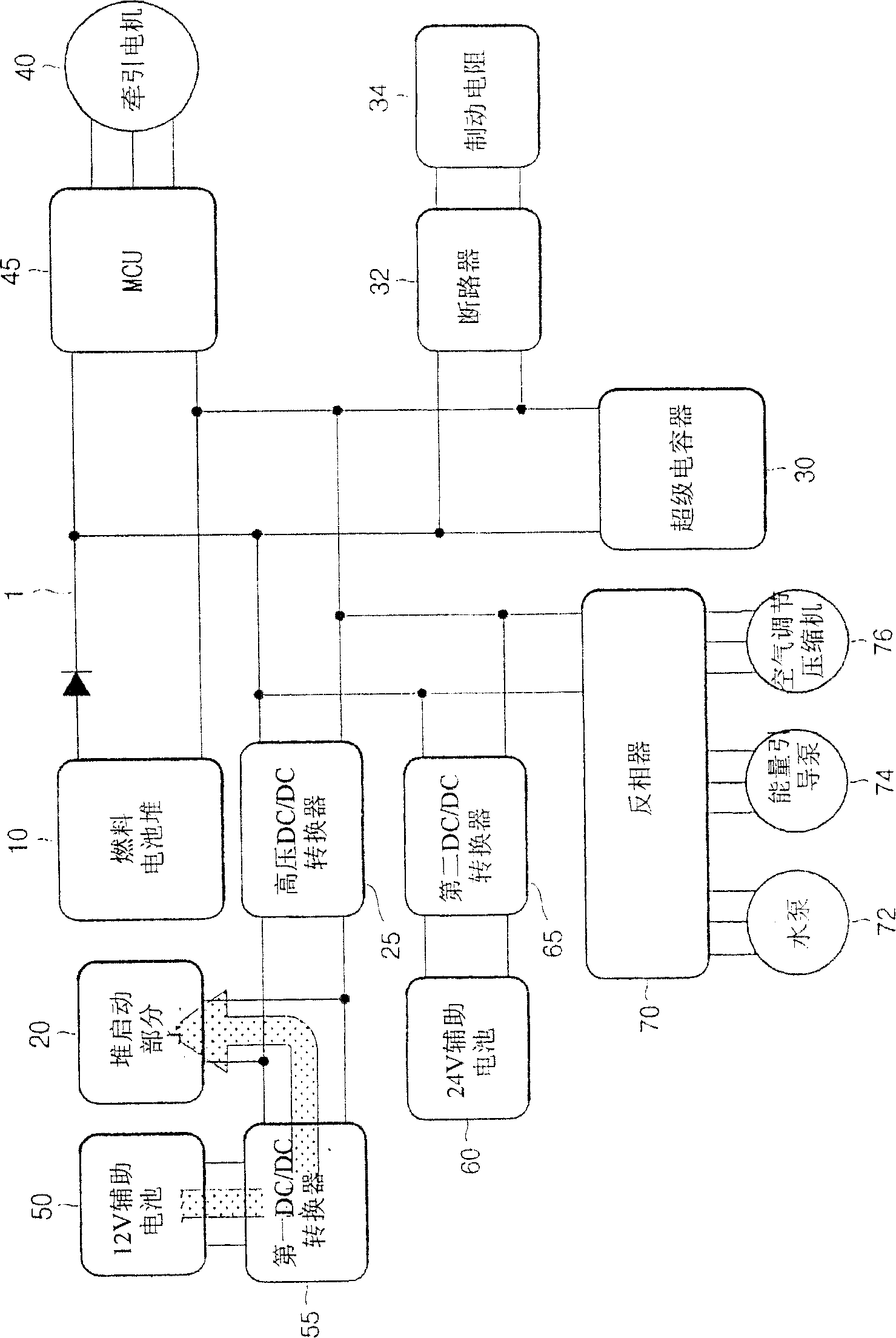
[0045] figure 1 is a power system diagram of a hybrid fuel cell bus according to an exemplary embodiment of the present invention.

[0046] refer to figure 1 , the power system of a hybrid fuel cell bus according to an exemplary embodiment of the present invention includes a fuel cell stack 10 .

[0047] The fuel cell stack 10 supplies high-voltage electric power of about 900V to the DC power line 1 of the passenger car.

[0048] For the normal operation of the fuel cell stack 10, thus establishing a voltage power of about 900V, the stack start-up part 20 involved in the start-up of the fuel cell stack such as hydrogen supply, air or oxygen supply, cooling etc. should be activated in advance.

[0049] Connecting the stack starting section 20 to the DC power line 1 of the passenger car enables power supply from the fuel cell stack 10 after star...


PUM


Abstract

The present invention provides a power system of a hybrid fuel cell bus, comprising: a first auxiliary battery supplying electric power to first electric parts designed for operation of a fuel cell vehicle; a second auxiliary battery supplying electric power to second electric parts designed for operation of an internal combustion engine vehicle; and a stack starting part electrically connected to one of the first and the second auxiliary batteries for operating the fuel cell stack.

Description

[0001] Cross References to Related Applications [0002] This application claims priority and benefits from Korean Patent Application No. 10-2006-0099024 filed with the Korean Patent Office on Oct. 11, 2006. technical field [0003] The present application relates to the power system of a hybrid fuel cell bus and its control method, and in particular to the power system of a hybrid fuel cell bus using a fuel cell and a supercapacitor as a power source and its control method, wherein the supercapacitor is an energy storage device connected to the fuel cell . Background technique [0004] A fuel cell is a device that directly converts the chemical energy of fuel into electrical energy through an electrochemical reaction. Since such fuel cells are highly efficient and have almost no emissions, fuel cell vehicles using fuel cells as a power source are being developed. [0005] Fuel cells in vehicles use hydrogen as fuel. Hydrogen gas is decomposed into hydrogen protons and el...

Claims


Application Information

Patent Timeline
Patent Type & Authority Applications(China)
IPC IPC(8): B60L11/18H02J7/00
CPCY02T90/34H01M16/006H01M8/04619Y02T90/32H01M8/04626H01M2250/20H01M8/0494Y02E60/50H01M8/04559B60L11/1887B60L11/1892H01M8/04947H01M8/04888H01M8/04567B60L2200/26B60L58/40B60L58/33Y02T90/40Y02T10/70Y02E60/10
Inventor 姜昊成
Owner HYUNDAI MOTOR CO LTD
Why Eureka
Try Eureka