Backlight module group and liquid crystal display

A backlight module and light source technology, which is applied to static indicators, instruments, optics, etc., can solve the problems of easy deformation of the optical diaphragm group, easy breakage of the lamp tube, and poor fit between the light source and the light guide plate, so as to reduce light leakage and The effect of bending and deformation

Inactive Publication Date: 2008-04-23
INNOCOM TECH SHENZHEN +1
View PDF0 Cites 7 Cited by
  • Summary
  • Abstract
  • Description
  • Claims
  • Application Information

AI Technical Summary

Problems solved by technology

[0006] In order to overcome the problems in the prior art that the lamp tube is easily broken, the light source and the light guide plate fit poorly, and the optical diaphragm group is easily

Method used


Image

  • Backlight module group and liquid crystal display
  • Backlight module group and liquid crystal display
  • Backlight module group and liquid crystal display

Examples


Embodiment Construction

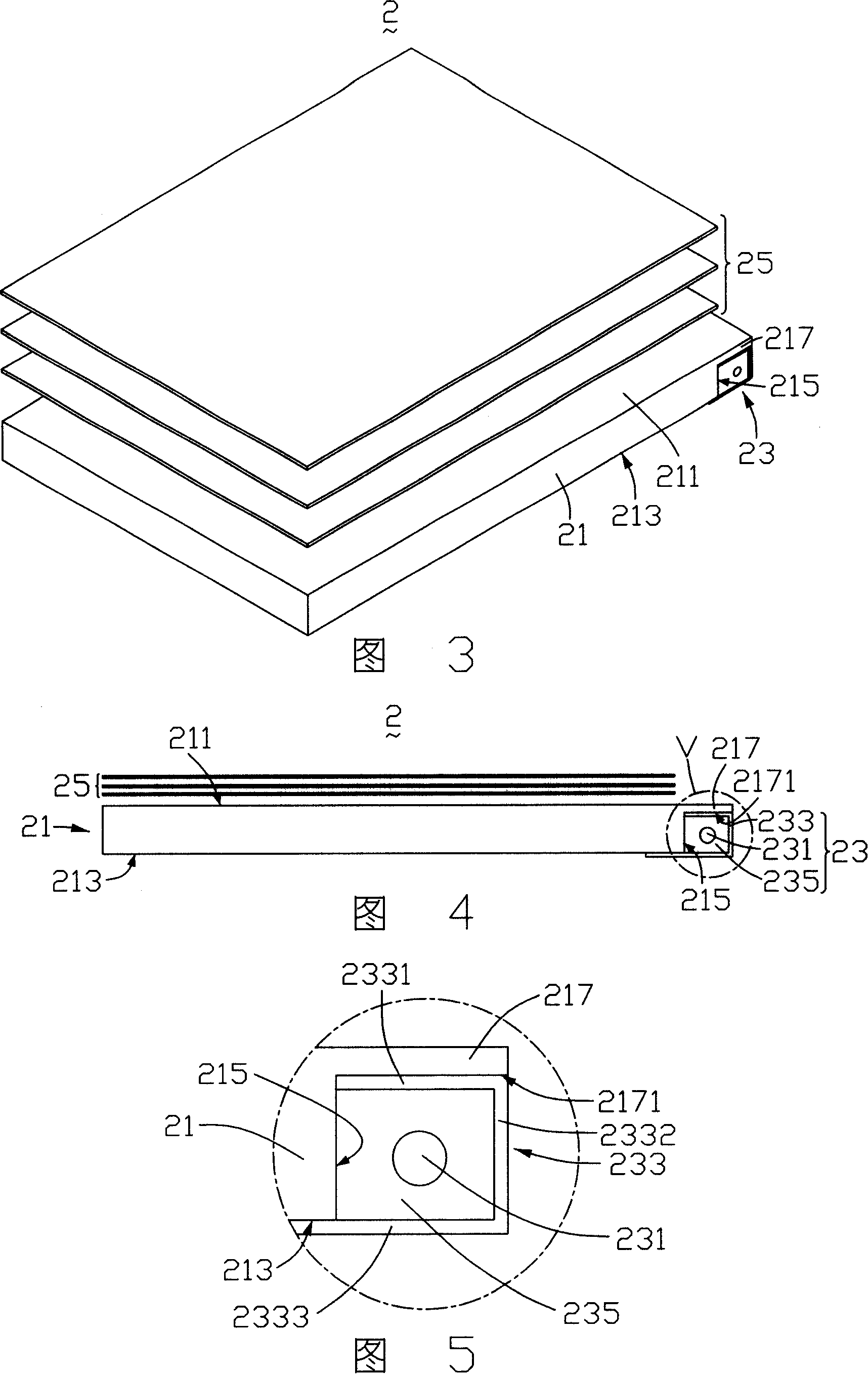
[0021] Please refer to FIG. 3 , which is a schematic perspective view of the first embodiment of the backlight module of the present invention. The backlight module 2 includes a light guide plate 21 , a light source 23 and an optical film set 25 placed on the light guide plate 21 .

[0022] Please also refer to FIG. 4 , which is a schematic structural diagram of the backlight module 2 shown in FIG. 3 . The light guide plate 21 includes a light emitting surface 211 , a bottom surface 213 opposite to the light emitting surface 211 , and a light incident surface 215 adjacent to the light emitting surface 211 . A protrusion 217 extends from the light emitting surface 211 of the light guide plate 21 on the light incident surface 215 side. The bump 217 can be manufactured by plastic molding or milling. The protrusion 217 includes a lower surface 2171 , the lower surface 2171 intersects the light incident surface 215 of the light guide plate 21 to form a receiving space (not shown)...


PUM


Abstract

The backlight module comprises a light guiding plate and at least one light source. Said light guiding plate comprises a light emergence face, and bottom face opposite to the light emergence face, and an light incidence face adjacent the light emergence face; said light source comprises a lamp tube and a reflection bowl; the light emergence face of the light guiding plate forms a bulge at the extension of the one side of the light incidence face; said bulge and the incidence face forms a holding space of holding the light source. The invention also provides a LCD display using said backlight module.

Description

technical field [0001] The invention relates to a backlight module and a liquid crystal display using the backlight module. Background technique [0002] Liquid crystal display is a non-self-luminous display device, and its display is mainly realized by liquid crystal molecules controlling external light beams to pass or not to pass through. Therefore, it is necessary to set up a corresponding backlight module or front light module to realize the display function. [0003] Please refer to figure 1 , which is a three-dimensional schematic diagram of a backlight module in the prior art. The backlight module 1 includes a light guide plate 11 , a light source 13 and an optical film set 15 placed on the light guide plate 11 . The light guide plate 11 includes a light emitting surface 111 , a bottom surface 113 opposite to the light emitting surface 111 , and a light incident surface 115 . The light source 13 is disposed on the light incident surface 115 side of the light guide...

Claims


Application Information

Patent Timeline
IPC IPC(8): G02F1/1335G02F1/133
Inventor 郑佑丞
Owner INNOCOM TECH SHENZHEN
Why Eureka
Try Eureka