Spun yarn taking-off apparatus

A traction equipment and spinning technology, applied in textiles and papermaking, conveying filamentous materials, and clustering of newly extruded filaments, etc., to achieve the effect of simple structure and improved quality

Active Publication Date: 2008-04-23
TMT MACHINERY INC
View PDF1 Cites 15 Cited by
  • Summary
  • Abstract
  • Description
  • Claims
  • Application Information

AI Technical Summary

Problems solved by technology

[0006] Therefore, in the conventional spinning drawing equipment, if the number of bobbins of one winding machine increases, in order to make the yarn inclination angle below a predetermined angle, it is necessary to extend the distance between the winding machine and the immediately preceding yarn feeding roller. There is a problem of large-scale equipment

Method used


Image

  • Spun yarn taking-off apparatus
  • Spun yarn taking-off apparatus
  • Spun yarn taking-off apparatus

Examples


Embodiment Construction

[0156] Two embodiments of the spinning take-up device of the present invention will be described below.

[0157] The first embodiment is a spinning and drawing device 100 for POY that winds POY (partially drawn yarn), and the second embodiment is a spinning and drawing device 200 for FDY that winds FDY (fully drawn yarn).

[0158] In addition to the configuration of the spinning and drawing device 100 for POY, a device for drawing and spinning is added to the spinning and drawing device 200 for FDY.

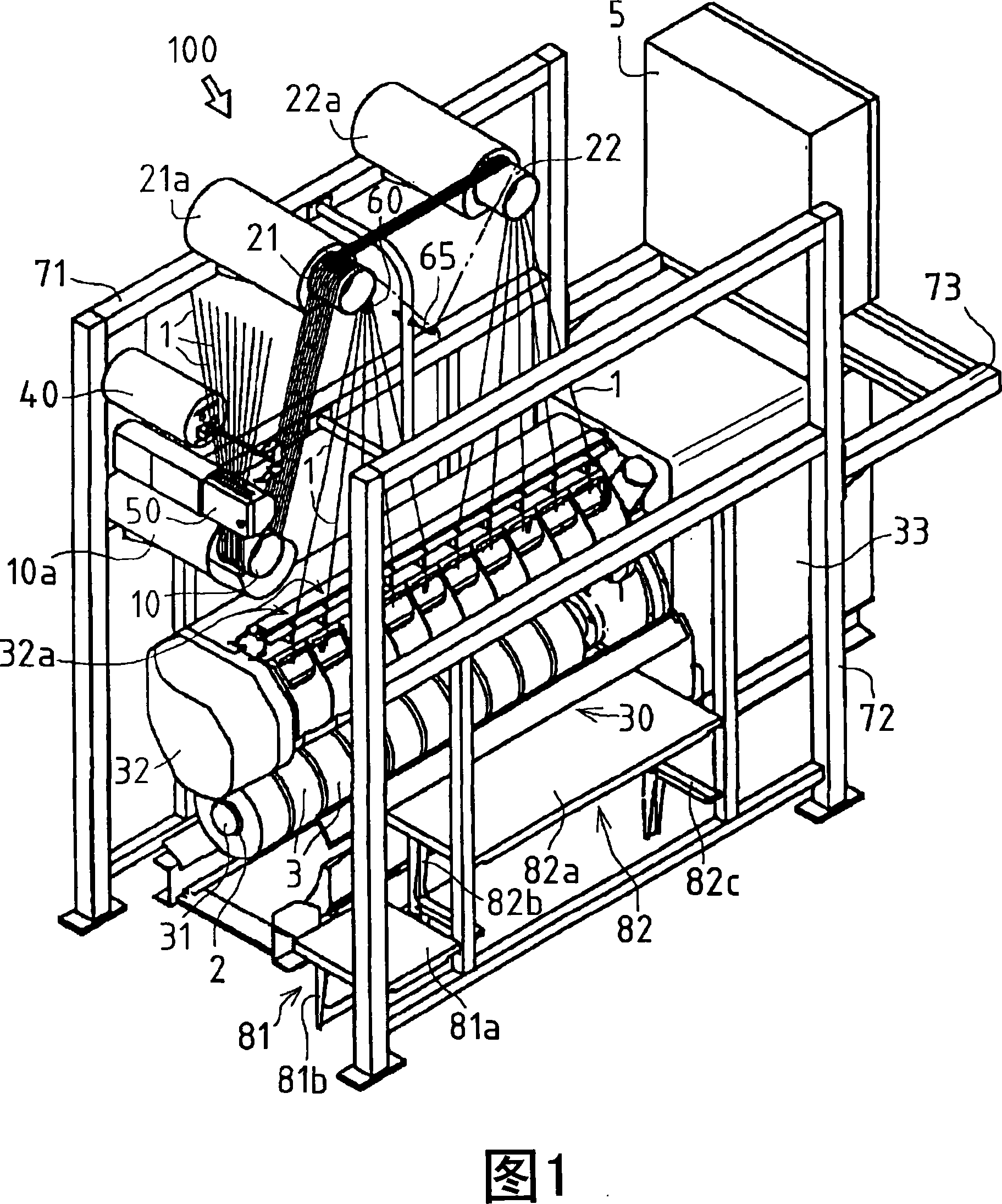
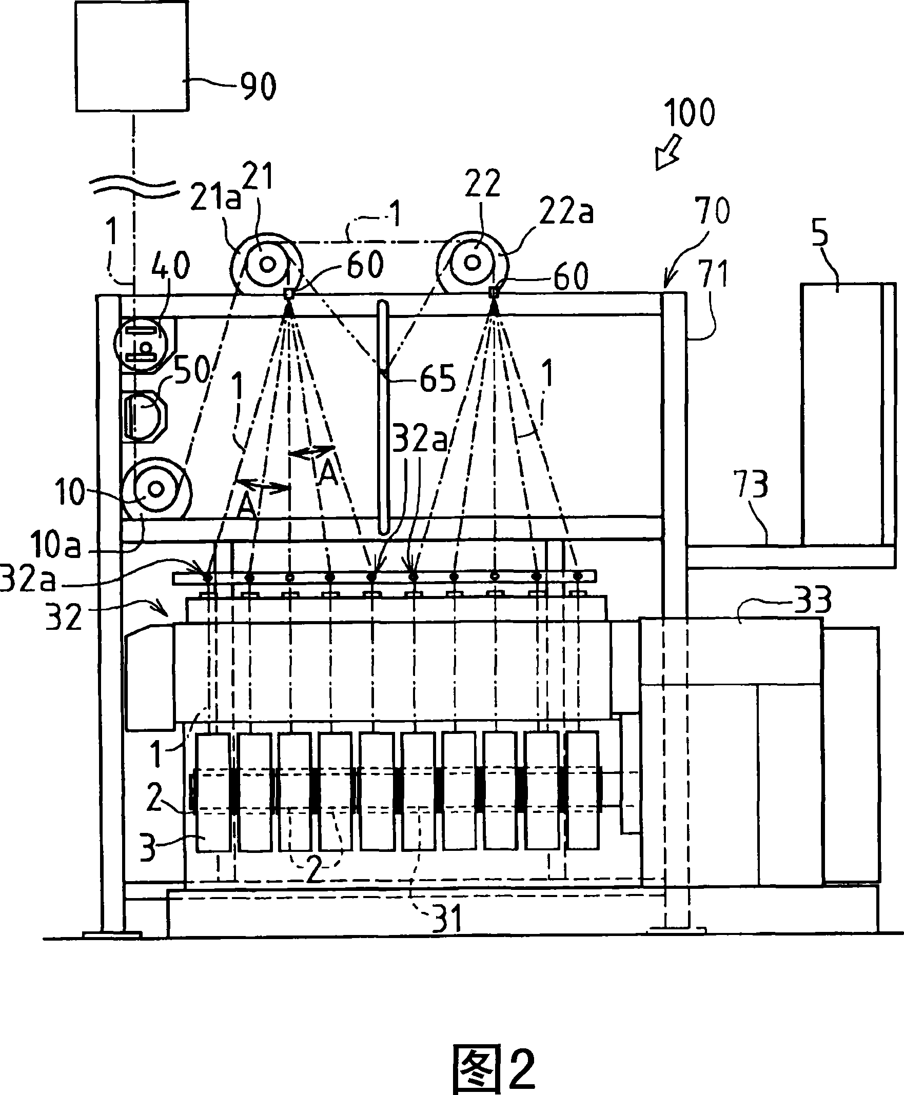
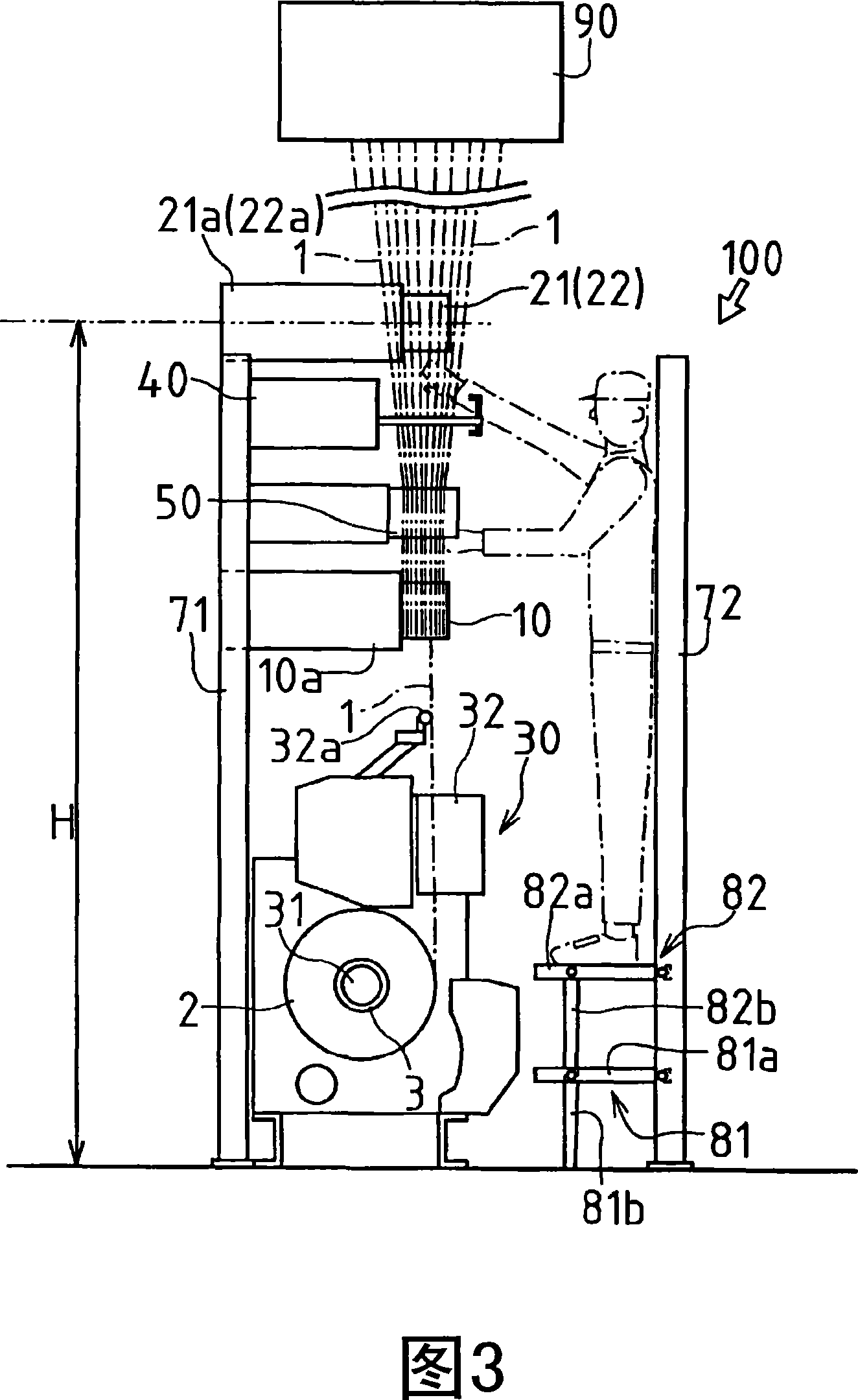
[0159] Next, the configuration of the POY spinning take-up device 100 will be described with reference to FIGS. 1 , 2 and 3 .

[0160] The spinning draw-up facility 100 for POY includes a winder 30 for winding a plurality of yarns supplied from a spinning head (molten resin discharge unit) 90 and multi-stage yarn supply rollers 10, 21, 22 (filament) 1; the yarn feeding rollers 10, 21, 22 are arranged between the spinning head 90 above and the winding machine 30 below, and a plur...


PUM


Abstract

A spun yarn taking-off apparatus (100) for POY, wherein ten pieces of yarns (1) spun out from a spinning head (90) are fed from an upper side to a lower side through a yarn feed roller (10) for conveyance on a first stage and last yarn feed rollers (21) and (22) on a second stage and concurrently wrapped around ten bobbins (2) installed on one winder (30). These ten pieces of yarns (1) are distributed to the plurality of last feed rollers (21) and (22) in unit of five pieces and then divided into pieces and led to the bobbins (2). The total circumferential lengths of the yarns (1) applied to the last yarn feed rollers (21) and (22) are the same.

Description

technical field [0001] The present invention relates to a spinning drawing device for winding a plurality of yarns spun from a spinning machine by a winding machine through a plurality of rollers. Background technique [0002] Conventional spinning and pulling equipment for synthetic fiber filaments uses a winder to wind a plurality of yarns spun from a spinning machine through a plurality of rolls. [0003] As shown in Fig. 1 of Patent Document 1, in this spinning drawing device, there is only one yarn feeding roller (yarn guide roller) arranged in front of the winding machine relative to one winding machine, so that the yarn after spinning The yarns spread out after an immediately preceding feed roller and are guided to bobbins mounted on a winder. [0004] Patent Document 1: Japanese Patent Laid-Open No. 2003-285972 [0005] Since the inclination angle of the yarn from the immediately preceding yarn supplying roller to the bobbin of the winding machine affects fluctuati...

Claims


Application Information

Patent Timeline
Patent Type & Authority Applications(China)
IPC IPC(8): D01D7/00B65H51/005B65H51/08B65H51/12
CPCB65H2701/3132B65H51/12D01D7/00B65H51/005
Inventor 温瑞明中川理
Owner TMT MACHINERY INC
Why Eureka
Try Eureka