Light source comprising led arranged in recess

A technology of light source and recess, applied in the field of light source, to achieve the effect of improving efficiency, reducing heat path and reducing thermal resistance

Inactive Publication Date: 2008-04-23
KONINK PHILIPS ELECTRONICS NV
View PDF1 Cites 0 Cited by
  • Summary
  • Abstract
  • Description
  • Claims
  • Application Information

AI Technical Summary

Problems solved by technology

[0007] The heat dissipation presents a limit to how long the LED can be operated or with what power the LED can be operated

Method used


Image

  • Light source comprising led arranged in recess
  • Light source comprising led arranged in recess

Examples


Embodiment Construction

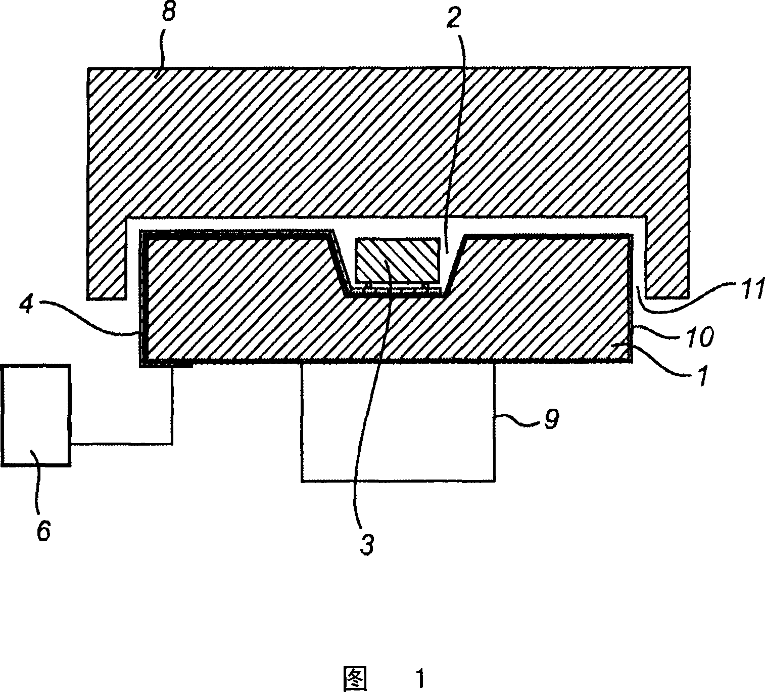
[0045] A schematic embodiment of a light source according to the invention is shown in FIG. 1 .

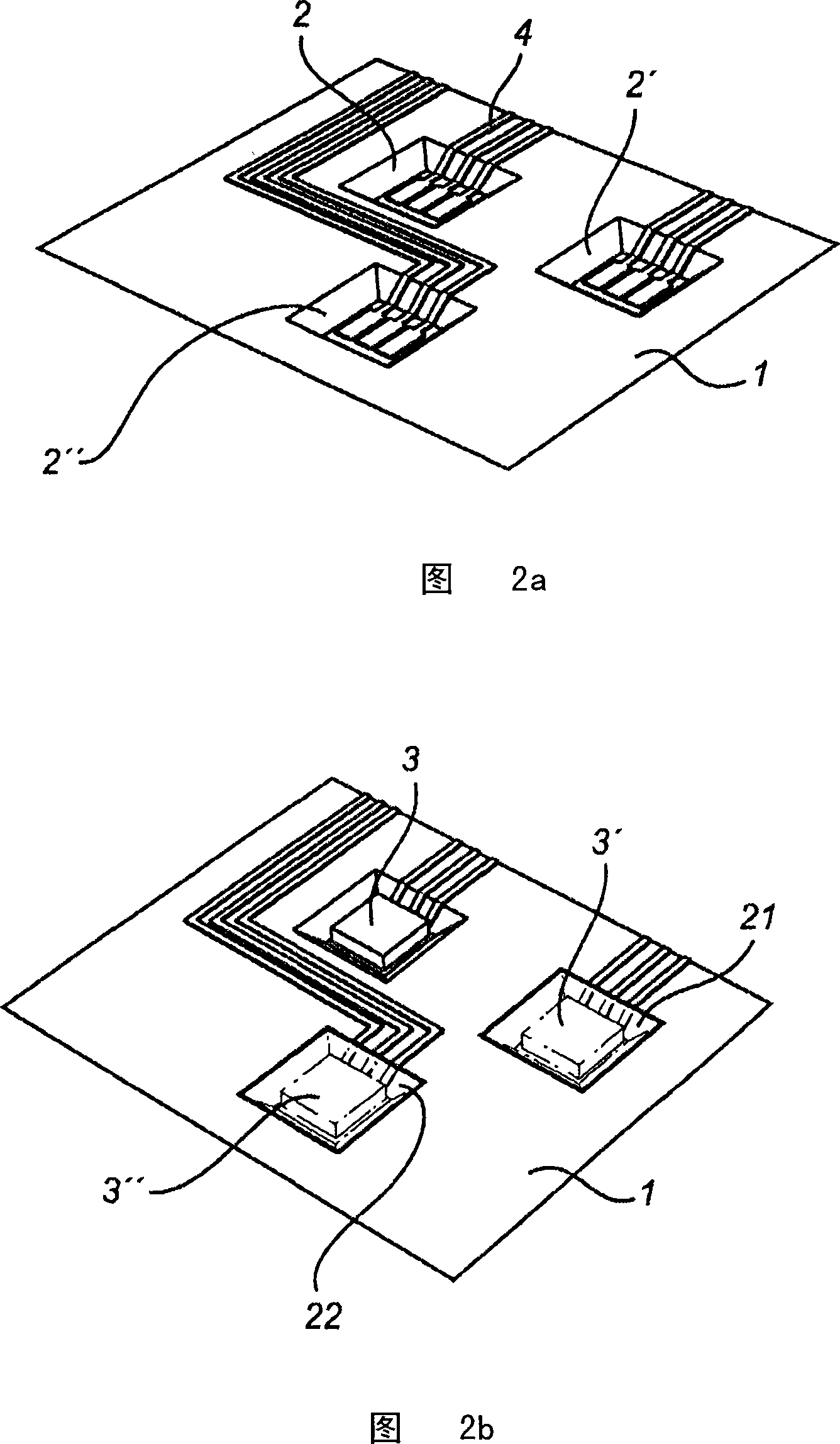
[0046] A silicon substrate 1 is provided, with SiO 2 The electrically insulating surface layer 10 of the substrate is provided with a recess 2 on the front side of the substrate. Light emitting diodes (LEDs) 3 are arranged in the recess 2 . The recess 2 is conical with an opening area larger than the bottom area.

[0047] The LED 3 is connected to the circuit 4 , arranged on the substrate 1 and located in the recess 2 . The connection between LED3 and circuit 4 is provided by solder bumps on the underside of the LED.

[0048]The circuit 4 passes through one side edge of the substrate and is connected to the LED driver unit 6 by contacts on the back side of the substrate 1 .

[0049] A light collimator 8 is provided so as to collimate the light emitted by the LED 3, and the light collimator includes a recess in which the substrate 1 is provided such that the collimator 8 partia...


PUM


Abstract

A light source comprising a substrate (1) having a first side and an opposing second side, at least one recess (2) being arranged in said first side of said substrate, a circuitry (4) at least partly arranged on said substrate (1), and at least one LED (3) being arranged in said at least one recess (2) and connected to said circuitry (4) is provided. The surface of said at least one recess (2) is continuous and is physically separated from said second side by substrate material. By arranging the LED in such a recess in the substrate, cross talk between adjacent LEDs is reduced, a good mechanical stability of the light source is maintained, and the thermal path through the substrate is reduced.

Description

technical field [0001] The invention relates to a light source comprising a substrate having a first side and an opposite second side, at least one recess arranged in said first side of said substrate, an electrical circuit at least partially arranged on said substrate, and at least one LED disposed in said at least one recess and connected to said circuit. Background technique [0002] An efficient and high-brightness LED array is currently considered as a light source. For this to work, multiple individual LEDs must be assembled on a substrate at fine pitches. [0003] In multiple LED applications, where several LEDs are placed on a substrate at fine pitches, it is also desirable to avoid crosstalk between LEDs, where light emitted from the sidewalls of multiple LEDs couples to adjacent LEDs (optionally of different colors) and is absorbed there. [0004] One way to prevent crosstalk between LEDs is to place the LEDs in recesses such that the walls of the recess prevent...

Claims


Application Information

Patent Timeline
Patent Type & Authority Applications(China)
IPC IPC(8): H01L33/00H01L33/58H01L33/60H01L33/62H01L33/64
CPCH01L33/642H01L33/62H01L33/58H01L33/60H01L2924/0002H01L2924/00
Inventor M·A·德萨姆伯K·范奥斯
Owner KONINK PHILIPS ELECTRONICS NV
Why Eureka
Try Eureka