Downlink loop detection method and device for tree network

A loop detection, tree network technology, applied in star/tree network, data exchange network, data exchange through path configuration, etc., can solve the problems of complex implementation, improve accuracy and reduce the pressure of sending and receiving packets Effect

Inactive Publication Date: 2008-04-30
NEW H3C TECH CO LTD
View PDF0 Cites 34 Cited by
  • Summary
  • Abstract
  • Description
  • Claims
  • Application Information

AI Technical Summary

Problems solved by technology

STP is a distributed algorithm that requires full support of switching devices in the network, that i

Method used


Image

  • Downlink loop detection method and device for tree network
  • Downlink loop detection method and device for tree network
  • Downlink loop detection method and device for tree network

Examples


Embodiment Construction

[0043] The present invention will be further described below in conjunction with the accompanying drawings and specific embodiments.

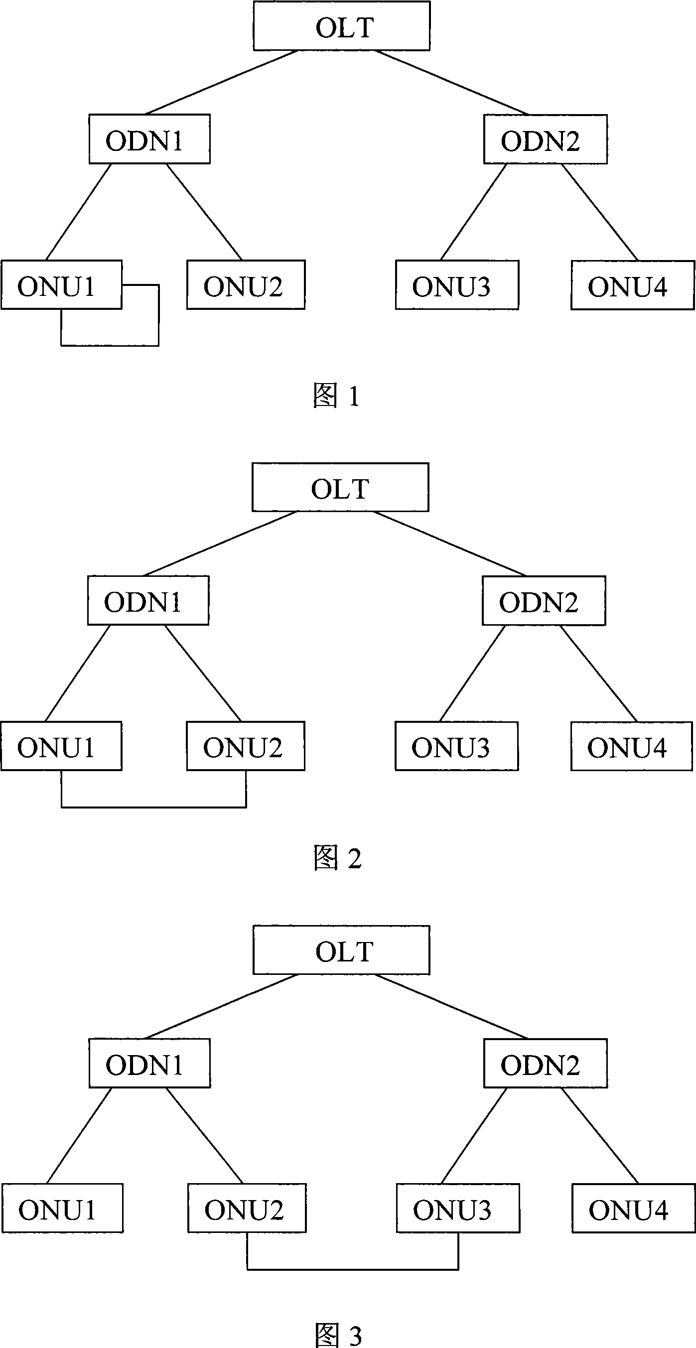
[0044] The loop detection method of the invention is used for detecting the downlink loop of the tree network. A tree network refers to a network that adopts a tree topology including EPON and GPON (Gigabit-capable PON, Gigabit Passive Optical Network); the downlink loop detection refers to the user side of the node that initiates the loop detection. Loop detection. In a tree network, when a network node forwards a message to a downstream node, it refers to forwarding the message to other network nodes directly connected to the network node except itself and the network node from which the message is sent.

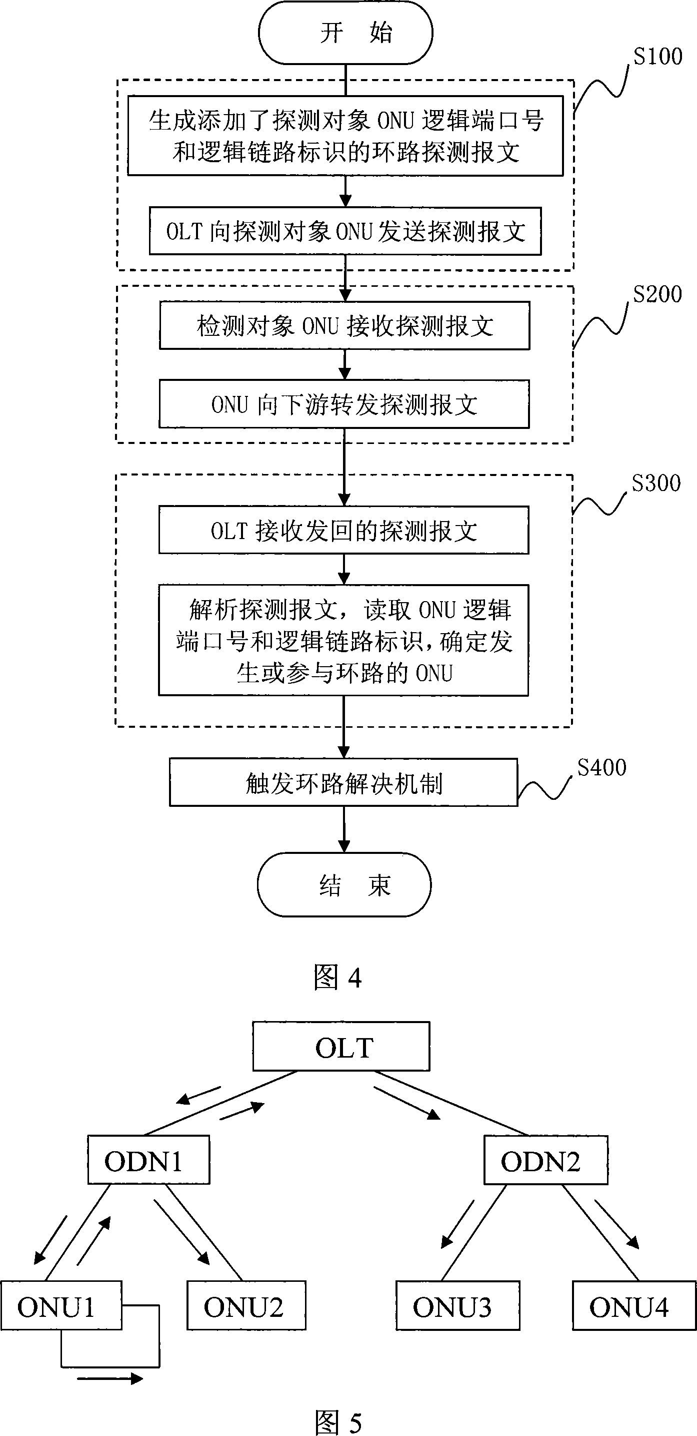
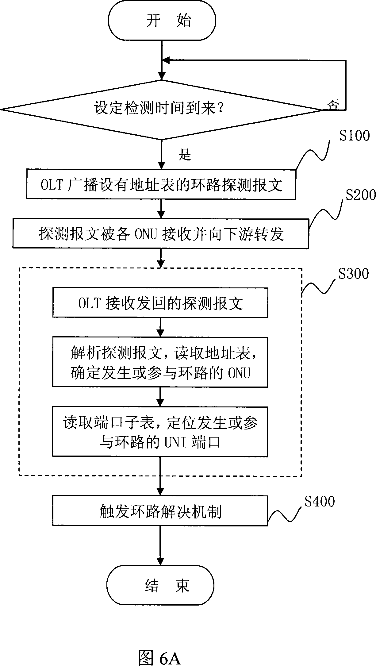
[0045] The loop detection method of the present invention comprises the following steps:

[0046] S100: The network side node sends a loop detection message with an address table set to its user side node;

[0047] S200: The user side node...


PUM


Abstract

The invention discloses a loop detection method used for detection of a downlink loop of a tree network, including the following steps: the network side node sends the loop detection packet to the user side node; the user side node receives and forwards the detection packet to the down stream; the network side node receives and analyzes the detection packet carrying the node information which is sent back from the user side node, so as to determine the user side node which generates or participates in the loop. The invention also discloses a loop detection device and an EPON network. The loop detection method of the invention can precisely position the generating position of the loop and reduce the transceiver packet pressure of the network side node.

Description

technical field [0001] The invention relates to a loop detection technology, in particular to a downlink loop detection method and device of an Ethernet Passive Optical Network (EPON for short) and an EPON network. Background technique [0002] In the prior art, as shown in Fig. 1, Fig. 2 and Fig. 3, there are three kinds of downlink loops that may appear in tree-type networking including EPON networking, the first type, as shown in Fig. 1, The loop on the same optical network unit (Optical Network Unit, referred to as ONU) as a user side node (including the single user network interface (User Network Interface, referred to as UNI) loop on the ONU and the loop between two UNI ports road); the second type, as shown in Figure 2, the loop between different ONUs under the same optical line terminal (OpticalLine Terminal, referred to as OLT) port; the third type, as shown in Figure 3, different OLT ports loop between. As shown in Figure 1, for the first type, it is said that ON...

Claims


Application Information

Patent Timeline
IPC IPC(8): H04L12/26H04L12/44H04L12/56
Inventor 况伟
Owner NEW H3C TECH CO LTD
Why Eureka
Try Eureka