
Method for recognizing fake real-time video

A real-time image and image technology, applied in the direction of analog security/toll system, closed-circuit television system, etc., can solve the problem of unrecognizable false images, etc., and achieve the effect of avoiding interception and tampering

Inactive Publication Date: 2008-05-07
SUN YAT SEN UNIV
View PDF0 Cites 9 Cited by
  • Summary
  • Abstract
  • Description
  • Claims
  • Application Information

AI Technical Summary

Problems solved by technology

Current digital surveillance systems are unable to identify such artifacts

Method used


Image

  • Method for recognizing fake real-time video
  • Method for recognizing fake real-time video

Examples


Embodiment Construction

[0036] The present invention will be further elaborated below in conjunction with the accompanying drawings.

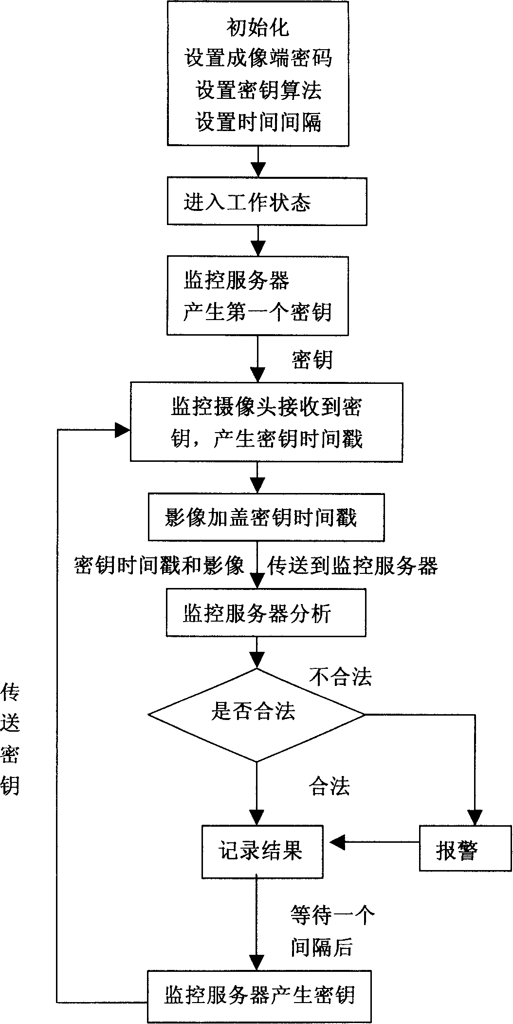
[0037] The purpose of the present invention is to enable the monitoring system to identify the tampered real-time image and issue a warning by regularly stamping the real-time image with a time stamp containing a key, so as to timely and accurately detect intruders or abnormal transmission of the monitoring system.

[0038] In the digital monitoring system, it is a method to prevent others from using false images to deceive the monitoring system and the monitoring administrator. For the module of encryption (that is, adding a key time stamp to the image), a key generator, key transceiver, key analyzer and alarm signal generator are added to the monitoring server.

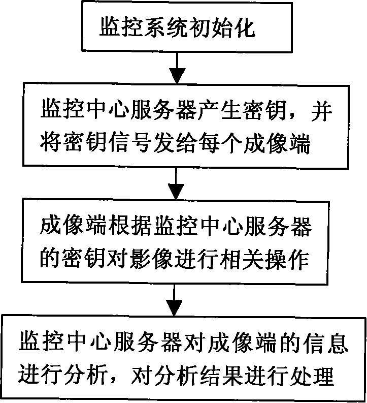
[0039] Such as figure 1 As shown, a method for identifying pseudo-real-time images, its main steps include:

[0040] 1) Monitoring system initialization;

[0041] 2) The monitoring center server generate...


PUM


Abstract

The present invention discloses a method for identifying pseudo real-time images, which relates to the field of digital monitoring technology. The method includes three steps; firstly, an imaging end is added with a clock, a check code generator, a key transceiver and an image encryption module; a monitoring server end is added with a key generator, a key transceiver, a key analyzer and an alarm signal generator. Secondly, according to the key sent by a monitoring center server, the current time recorded by the clock and the initial password set on the imaging end, the method utilizes a key generation algorithm and the check code generator on the imaging end to produce a key time stamp containing a check code, the key time stamp is then transmitted to the monitoring center server; Thirdly, the key analyzer decrypts the key time stamp by a monitoring center and obtains analysis results. The present invention can intelligently identify the authenticity of a real-time image and effectively prevent the real-time image from being intercepted and falsified by an intruder in the course of transmission, so the monitoring is more authentic.

Description

technical field [0001] The invention belongs to the technical field of digital monitoring, in particular to a technology for preventing others from deceiving the monitoring system by false images in the digital monitoring system. Background technique [0002] The digital monitoring system is a device that collects video information by digital camera equipment and transmits it digitally to the monitoring center through a wired network. The 100M and Gigabit networks can provide sufficient network bandwidth to support multiple high-quality concurrent video streams. A new generation of monitoring system. [0003] At present, there are many imaging systems used in monitoring, but none of them have the function of identifying fake real-time scene images. For example, intercept a point from the middle of the transmission line to deceive the monitoring system and monitoring management personnel by playing historical video and other methods. At this time, the monitoring personnel an...

Claims


Application Information

Patent Timeline
Patent Type & Authority Applications(China)
IPC IPC(8): H04N7/18H04N7/16
Inventor 徐永举罗笑南
Owner SUN YAT SEN UNIV
Learn More