Separating elastic tube high-speed spinning spindle

The technology of spinning spindle and elastic tube is applied in the field of high-speed spinning spindle with separate elastic tube, which can solve the problem of no axial buffer and shock absorption function, and achieve the effects of stable and reliable operation, enhanced rigidity and bearing capacity, and reduced amplitude

Inactive Publication Date: 2008-05-14
HENGYANG TEXTILE MACHINERY MANUFACTORY
View PDF0 Cites 5 Cited by
  • Summary
  • Abstract
  • Description
  • Claims
  • Application Information

AI Technical Summary

Problems solved by technology

The traditional upper and lower support separated type ingot has a fixed upper support and a floating lower support, wh

Method used


Image

  • Separating elastic tube high-speed spinning spindle

Examples


Embodiment Construction

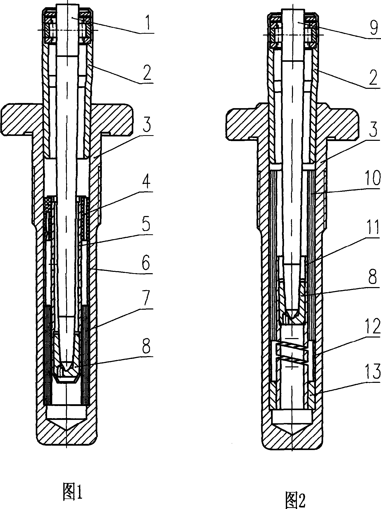
[0008] Among Fig. 1: 1. spindle rod, 2. upper support, 3. spindle foot, 4. elastic ring, 5. lower support tube, 6. positioning sleeve, 7. damper, 8 spindle bottoms.

[0009] The present invention will now be described in detail in conjunction with the embodiment shown in FIG. 2 .

[0010] The separated elastic tube high-speed spinning spindle includes a spindle base and a rod disc. The lower support tube 11 in the spindle base is made of metal tube material, and two spiral grooves are milled on the top to make it have good elasticity. The lower end is clipped into the spindle foot 3 In the lower support seat 13 at the bottom of the hole, the lower support seat 13 mainly plays a role in positioning and fixing the lower support. It can be made of metal, plastic, powder metallurgy, etc. into a cylindrical shape, and the ingot bottom 8 is placed on the lower support of the spiral groove. In the upper hole of the tube 11, the bottom end of the ingot rod 9 is inserted into the 8 hol...


PUM


Abstract

A separate elastic tube high-speed spinning spindle in a ring spinning frame, characterized in that the lower support tube in the spindle seat has a spiral groove, and the lower end is inserted into the lower support seat at the bottom of the spindle foot hole, and the bottom of the spindle is placed on the spiral In the upper hole of the lower support tube above the groove, the bottom end of the spindle rod is inserted into the bottom hole of the ingot, the positioning sleeve is sleeved outside the lower support tube above the lower support seat, and the damper is sleeved between the upper part of the lower support tube and the inner wall of the spindle foot. Between, the lower end is close to the top of the positioning sleeve. A spiral groove is added to the lower support tube, and the bottom of the ingot is moved above the spiral groove, so that the lower support has both radial and axial buffering and shock-absorbing functions. The shortening of the spindle rod enhances the rigidity and bearing capacity of the spindle rod, which can effectively reduce the spindle vibration amplitude, and the operation is stable and reliable.

Description

technical field [0001] The invention relates to a component of a textile ring spinning frame, in particular to a high-speed spinning spindle of a separated elastic tube. Background technique [0002] Spindle is the key component that plays the role of twisting and winding in the spinning frame. The spindle of the ring spinning frame is composed of spindle base, rod disc and other components. Among them, the spindle bladder in the spindle base has a separate upper and lower support type and a metal elastic tube for upper and lower support. There are two types of connection structure, and the upper and lower supports use metal elastic tubes to connect the ingot. Because of the use of metal elastic tubes, the lower support not only has a radial buffer and shock absorption function, but also has a certain buffer and shock absorption function in the axial direction. The traditional upper and lower support separated type ingot is fixed on the upper support and floating on the lowe...

Claims


Application Information

Patent Timeline
IPC IPC(8): D01H7/04D01H7/08
Inventor 冯立晨蔡金友张明鸿
Owner HENGYANG TEXTILE MACHINERY MANUFACTORY
Why Eureka
Try Eureka