Zoom lens, image pickup device and information carrying terminal device
A zoom lens and photographic device technology, applied in television, optics, instruments, etc., can solve the problem of not being able to realize the half-image angle and wide-image angle, and achieve the effect of full miniaturization and high performance
- Summary
- Abstract
- Description
- Claims
- Application Information
AI Technical Summary
Problems solved by technology
Method used
Image
Examples
Embodiment 1
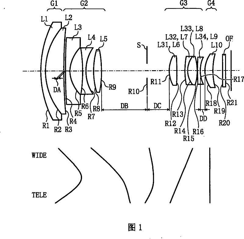
[0178] figure 1 Shown is the configuration of the zoom lens optical system according to Embodiment 1 of the present invention.
[0179] figure 1 Shown is the configuration at the short focal length end, that is, the wide-angle end (Wide end) of the zoom lens optical system according to Embodiment 1 of the present invention.
[0180] figure 1 The shown zoom lenses are arranged sequentially from the object side to the image side: first lens L1, second lens L2, third lens L3, fourth lens L4, fifth lens L5, aperture stop S, sixth lens L6, The seventh lens L7, the eighth lens L8, the ninth lens L9, the tenth lens L10, and the optical filter OF form images behind the optical filter OF having various optical filtering functions. At this time, the first lens L1 to the second lens L2 constitute the first lens group G1, the third lens L3 to the fifth lens L5 constitute the second lens group G2, and the sixth lens L6 to the ninth lens L9 constitute the third lens group G3. , the 10th...
Embodiment 2
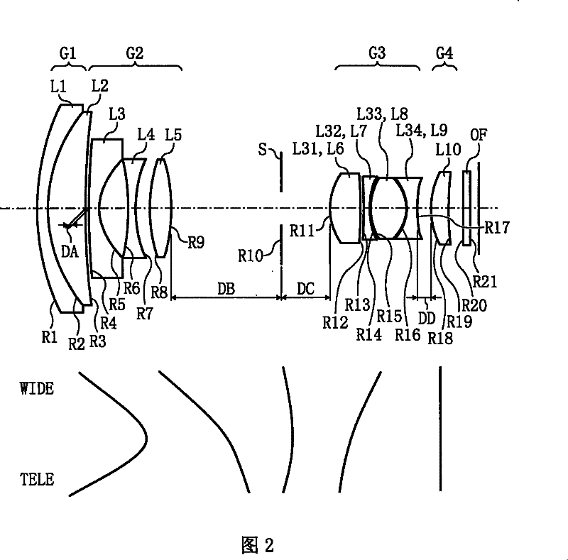
[0219] figure 2 Shown is the configuration of the zoom lens optical system according to Embodiment 2 of the present invention.
[0220] figure 2 Shown is the configuration at the short focal length end, that is, the wide-angle end, of the zoom lens optical system according to Embodiment 2 of the present invention.
[0221] figure 2 The shown zoom lens is the same as the zoom lens related to Example 1, and is provided in order from the object side: the first lens L1, the second lens L2, the third lens L3, the fourth lens L4, the fifth lens L5, the aperture The diaphragm S, the sixth lens L6, the seventh lens L7, the eighth lens L8, the ninth lens L9, the tenth lens L10 and the optical filter OF form images behind the optical filter OF having various optical filtering functions. At this time, the first lens L1 to the second lens L2 constitute the first lens group G1, the third lens L3 to the fifth lens L5 constitute the second lens group G2, and the sixth lens L6 to the ni...
Embodiment 3
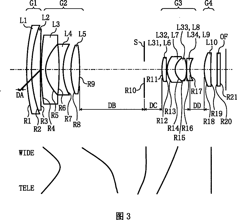
[0257] image 3Shown is the configuration of the zoom lens optical system according to Embodiment 3 of the present invention.
[0258] image 3 Shown is the configuration at the short focal length end, that is, the wide-angle end (Wide end) of the zoom lens optical system according to Embodiment 3 of the present invention.
[0259] image 3 The shown zoom lenses are arranged sequentially from the object side to the image side: first lens L1, second lens L2, third lens L3, fourth lens L4, fifth lens L5, aperture stop S, sixth lens L6, The seventh lens L7, the eighth lens L8, the ninth lens L9, the tenth lens L10, and the optical filter OF form images behind the optical filter OF having various optical filtering functions. At this time, the first lens L1 to the second lens L2 constitute the first lens group G1, the third lens L3 to the fifth lens L5 constitute the second lens group G2, and the sixth lens L6 to the ninth lens L9 constitute the third lens group G3. , the 10th ...
PUM
 Abstract
Description
Claims
Application Information
 - R&D
- Intellectual Property
- Life Sciences
- Materials
- Tech Scout
- Unparalleled Data Quality
- Higher Quality Content
- 60% Fewer Hallucinations
Browse by: Latest US Patents, China's latest patents, Technical Efficacy Thesaurus, Application Domain, Technology Topic, Popular Technical Reports.
© 2025 PatSnap. All rights reserved.Legal|Privacy policy|Modern Slavery Act Transparency Statement|Sitemap|About US| Contact US: help@patsnap.com


