Position detecting method and device, patterning device, and subject to be detected

A detection method and technology of a detection device, which are applied to the photoengraving process of the pattern surface, the exposure device of the photoengraving process, the testing/measurement of semiconductor/solid-state devices, etc., can solve the problems of increasing the processing time of the substrate and reducing the productivity, etc.

Inactive Publication Date: 2008-05-14
DAINIPPON SCREEN MTG CO LTD
View PDF1 Cites 18 Cited by
  • Summary
  • Abstract
  • Description
  • Claims
  • Application Information

AI Technical Summary

Problems solved by technology

[0006] However, if the secondary positioning (high magnification and low magnification secondary shooting) of pre-positioning and fine positioning is performed in this way, it will increase the processing time for the substrate and reduce the productivity. Therefore, improvement measures are expected.

Method used


Image

  • Position detecting method and device, patterning device, and subject to be detected
  • Position detecting method and device, patterning device, and subject to be detected
  • Position detecting method and device, patterning device, and subject to be detected

Examples


no. 1 approach

[0052] 1-1. Structure

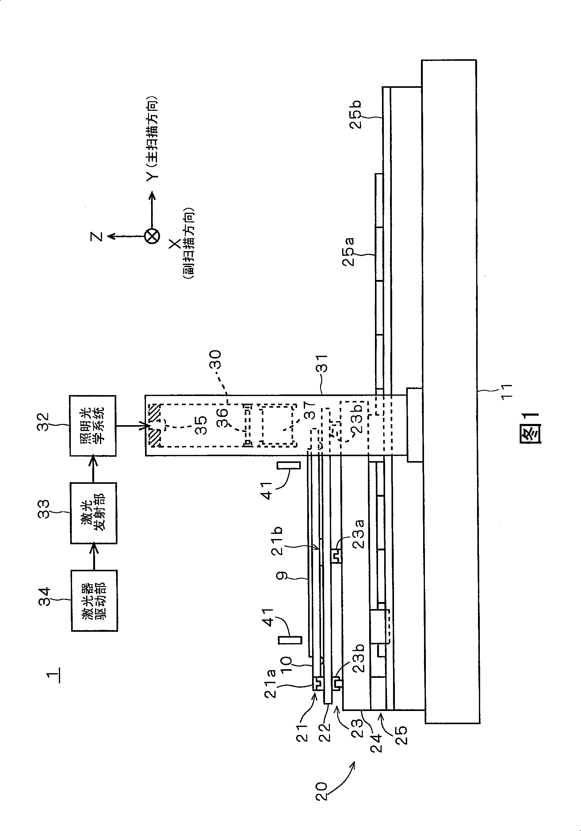
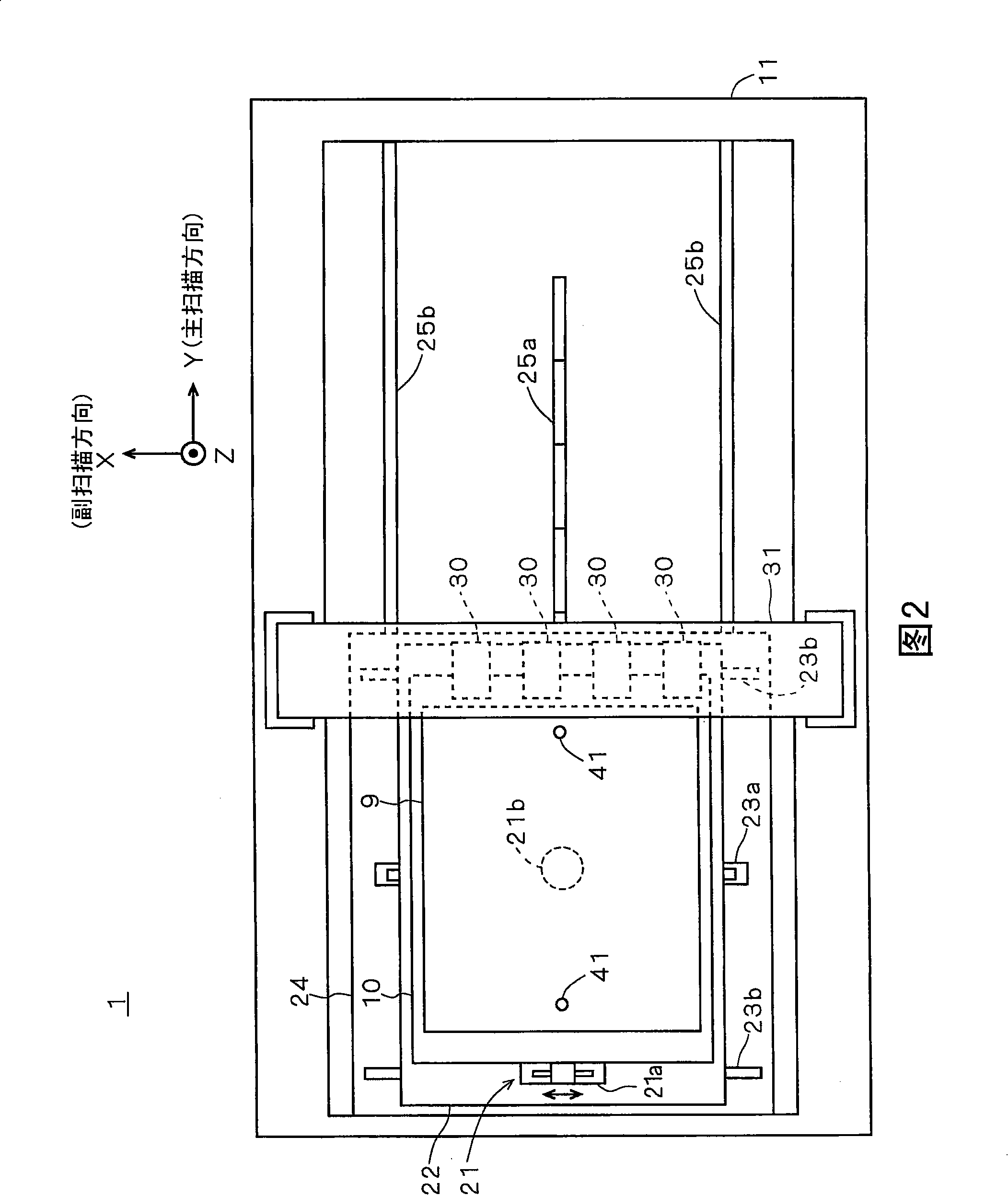
[0053] 1 and 2 are diagrams of the structure of a pattern drawing device 1 having the function of the position detection device of the first embodiment. FIG. 1 is a side view, and FIG. 2 is a plan view. In the process of manufacturing a color filter of a liquid crystal display device, the pattern drawing device 1 is used to form a glass substrate for a color filter (hereinafter referred to as a "substrate") on which a photosensitive material (color-resist in this embodiment) is formed. 9. A device for drawing prescribed patterns on 9. As shown in FIGS. 1 and 2, the pattern drawing apparatus 1 mainly includes a base 11, a stage 10 on which a substrate 9 is loaded, a drive unit 20 that drives the stage 10 with respect to the base 11, a plurality of exposure heads 30, and a substrate. 9 two cameras 41 for positioning.

[0054] In addition, in the following description, when indicating the direction and orientation, the three-dimensional XYZ rectangular coordin...

no. 2 approach

[0109] Next, the second embodiment will be described. Hereinafter, the description will be mainly based on the differences from the first embodiment. In the first embodiment, the positioning marks of the plurality of positioning marks 60 respectively record their own positions. In contrast, in the second embodiment, each of the plurality of positioning marks 60 does not record its own position, but records identification information identifying itself from other positioning marks 60, and the position of the positioning mark 60 can be specified based on the identification information.

[0110] Figure 14 It is a diagram illustrating the content of the information recorded in each positioning mark 60 included in one positioning area 92 of the second embodiment. In each positioning mark 60 in the figure, the content of the information indicated by the positioning mark 60 is shown in parentheses. As shown in the figure, each positioning mark 60 does not record its own position, but r...


PUM


Abstract

The present invention provides a technology capable of detecting the position of an object to be detected with one shot. The pattern drawing device collectively forms a plurality of positioning marks (60) within a specified range as a positioning area (92) on the substrate (9) to be processed, and these positioning marks record the reference positions on the substrate (9) respectively. The information record code of the relative position with itself. When positioning the substrate (9), since the positioning region (92) in which a plurality of positioning marks (60) are concentrated is captured to obtain an image, even if the imaging magnification is set to a high magnification and the imaging range is narrowed, multiple positioning marks (60) can be One of the positioning marks (60) is included in the image. And, one positioning mark (60) contained in the image as an image is set as a fixation mark, and the position of the substrate (9) is derived from the fixation mark in the image, so that the substrate (9) can be detected by one shot. s position.

Description

Technical field [0001] The present invention relates to a technique for detecting the position of an object to be detected arranged in a predetermined arrangement area. Background technique [0002] In liquid crystal display devices, color filter substrates, liquid crystal display devices or plasma display devices and other flat-panel display (FPD) glass substrates, semiconductor substrates, printed circuit boards and other substrates such as pattern drawing devices that draw fine patterns on substrates, etc. To perform high-precision processing, it is necessary to accurately align the substrate to be processed at a predetermined ideal position. Therefore, various technical solutions have been proposed to detect the position of a substrate loaded in a predetermined arrangement area. [0003] For example, in the conventional representative technology, a predetermined position on the substrate is marked with an alignment mark in advance, and the periphery of the alignment mark is c...

Claims


Application Information

Patent Timeline
Patent Type & Authority Applications(China)
IPC IPC(8): G03F7/20G03F9/00
CPCG03F9/7088G03F9/7046G03F9/7076G03F7/70391H01L22/00
Inventor 井上正雄
Owner DAINIPPON SCREEN MTG CO LTD
Why Eureka
Try Eureka