One point coaxial feed low profile back-cavity circularly polarized antenna

A circularly polarized antenna and coaxial feeding technology, applied in the direction of slot antenna, circuit, radiation element structure, etc., can solve problems such as complex processing, achieve fewer structural parameters, reduce outline and manufacturing costs, shorten design and The effect of optimized time

Inactive Publication Date: 2008-05-14
舟山乐讯智能科技有限公司
View PDF0 Cites 24 Cited by
  • Summary
  • Abstract
  • Description
  • Claims
  • Application Information

AI Technical Summary

Benefits of technology

The inventors have developed an improved version of a small square loop (SRL) dipole used for communication purposes called Cassegrain Antenna or Microwave Antennance Factor (MFA). These SRL elements use special materials like ceramics instead of conventional metals such as gold. They also reduce their size compared to other types of antennas due to its compact shape. By utilizing these techniques, they make it easier to create smaller components while maintaining good radio frequency characteristics over longer periods of operation.

Problems solved by technology

Technological Problem: Current designs of circularly oriented dipole antennas require multiple layers or spiraling processes that result in increased thicknesses while maintaining desired properties like resonance match between different parts (transmitting/receiving). Additionally, current circularly conductive materials often exhibit poor stability over long periods of operation without being able to integrate themselves within electronic devices.

Method used


Image

  • One point coaxial feed low profile back-cavity circularly polarized antenna
  • One point coaxial feed low profile back-cavity circularly polarized antenna
  • One point coaxial feed low profile back-cavity circularly polarized antenna

Examples


Embodiment Construction

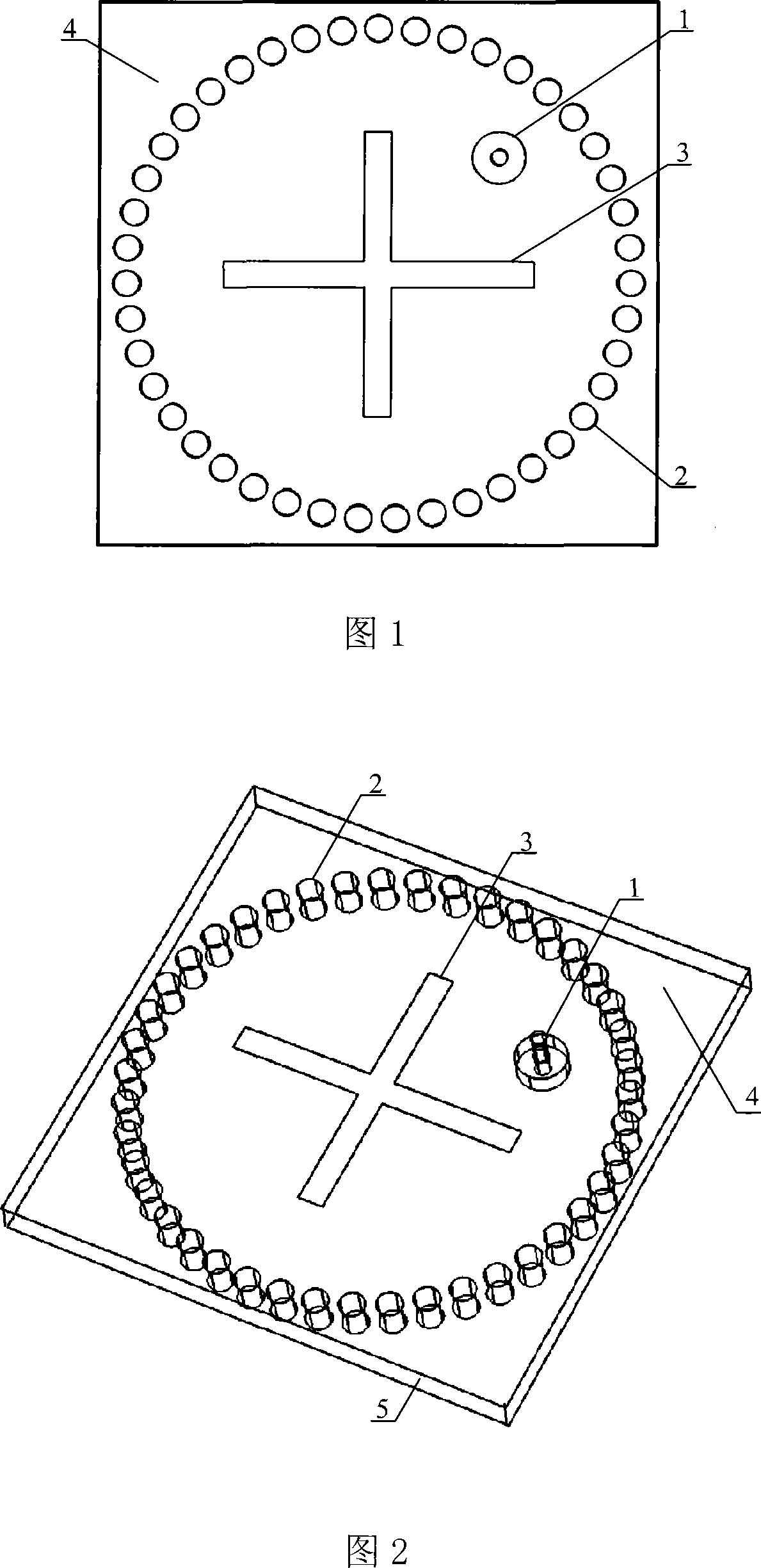
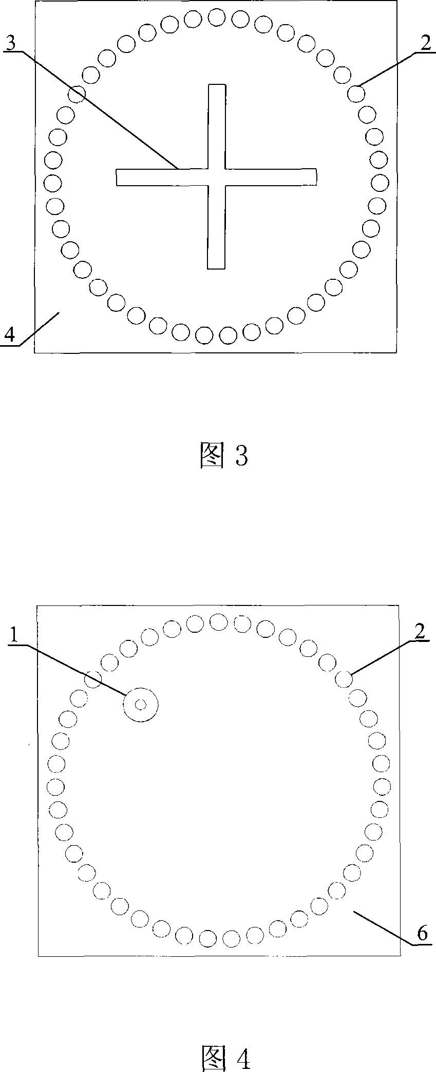
[0021] As shown in Figures 1 and 2, the single-point coaxial feed low-profile cavity-backed circularly polarized antenna includes a Rogers5880 dielectric substrate 5 with a thickness of 0.5 mm, and the two sides of the dielectric substrate 5 are coated with metal layers, which are respectively the upper metal layer 4 and the lower metal layer 6, wherein the lower metal layer 6 is used as a stratum. Through the upper metal layer 4, the dielectric substrate 5 and the lower metal layer 6, a diameter of 1 mm is opened, and the inner wall of the through hole is plated with metal to form a metallized through hole 2; a plurality of metallized through holes 2 are arranged in a circular order to form a The circular substrate-integrated waveguide cavity and the metallized through-holes 2 constituting the substrate-integrated waveguide cavity have the same hole spacing, which is 1.35 mm. As shown in Figure 3, the upper metal layer 4 is etched in the area of ​​the substrate integrated wav...


PUM


Abstract

The invention relates to a single-point coaxial feeding low-profile cavity-backed circularly polarized antenna. Ordinary cavity-backed circularly polarized antennas have complex structures, large volumes, and high manufacturing costs. In the invention, metal layers are plated on both sides of the dielectric substrate, and the upper metal layer is etched with two mutually perpendicular rectangular slits for radiating energy. Through the upper metal layer, the dielectric substrate and the lower metal layer, a plurality of metallized through holes arranged in a circle are opened to form a circular cavity. At the appropriate position of the angle bisector of two mutually perpendicular elongated radiation slots in the cavity area, a coaxial probe is connected through the lower metal layer and the dielectric substrate as a feed structure. Compared with the existing cavity-backed circularly polarized antenna composed of a metal cavity, the cavity of the present invention is manufactured by common PCB technology, so that the antenna has a small profile and low manufacturing cost.

Description


Claims


Application Information

Patent Timeline
Owner 舟山乐讯智能科技有限公司
Why Eureka
Try Eureka