Condenser type non-contact manifold ring and power supply device using the same

A non-contact, capacitive technology, applied in capacitors, fixed capacitors, conversion equipment that can be converted to DC without intermediate conversion, etc., can solve the problems of unstable power supply current, poor stability, and easy damage, and achieve reliable High performance, good stability, and flexible relative motion

Inactive Publication Date: 2008-05-21
HARBIN INST OF TECH
View PDF1 Cites 6 Cited by
  • Summary
  • Abstract
  • Description
  • Claims
  • Application Information

AI Technical Summary

Problems solved by technology

[0005] In order to solve the problems of easy damage and poor stability of the existing contact collector ring, and the unstable power supply current output to the load by the power supply device using the collector ring, the present invention provides a capacitive non-contact current collector ring and power supply device using said collector ring

Method used


Image

  • Condenser type non-contact manifold ring and power supply device using the same
  • Condenser type non-contact manifold ring and power supply device using the same
  • Condenser type non-contact manifold ring and power supply device using the same

Examples


specific Embodiment approach 1

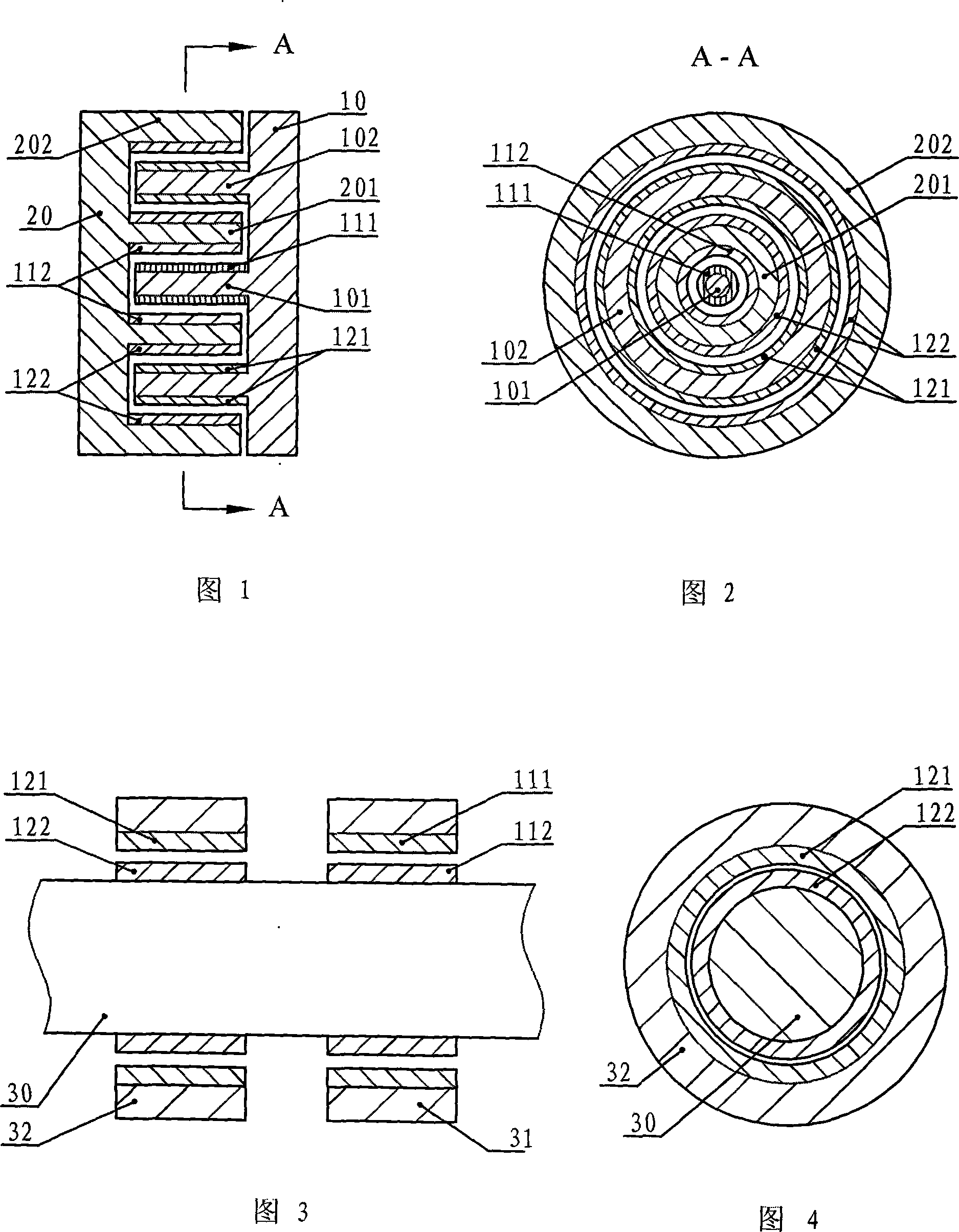
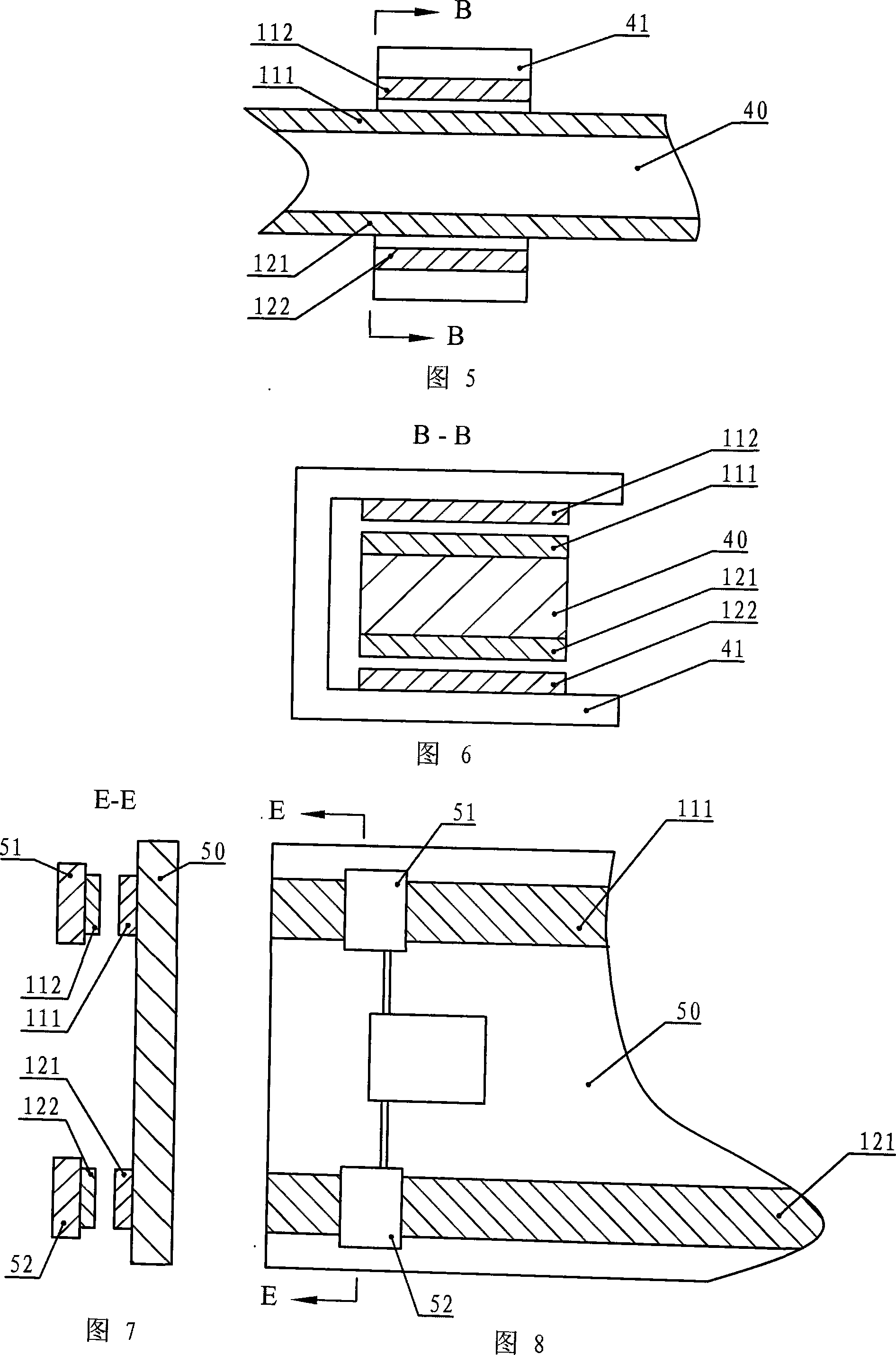
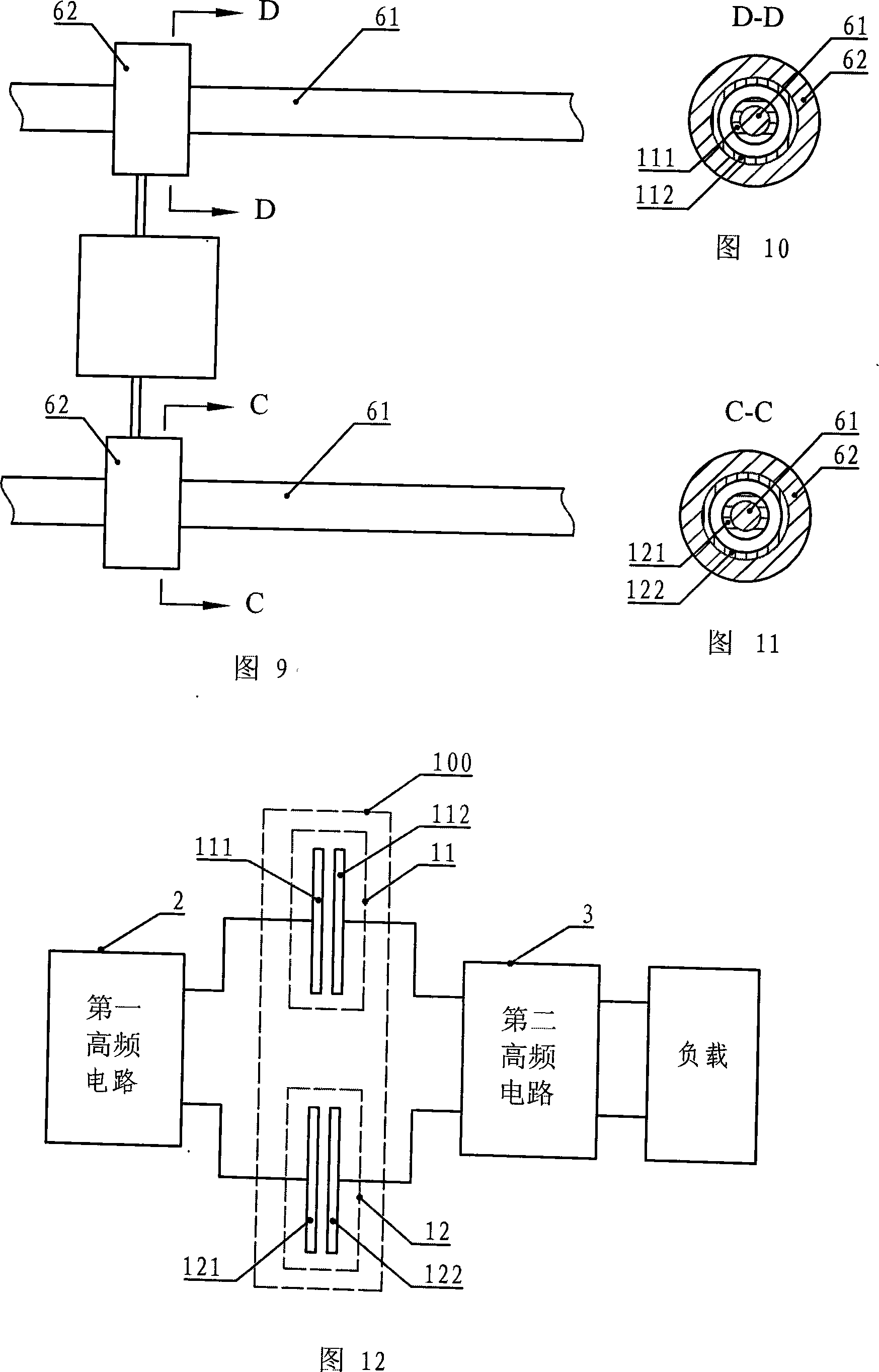
[0014] Embodiment 1: The capacitive non-contact slip ring described in this embodiment is composed of a first capacitor 11 and a second capacitor 12, and the two electrode plates of the first capacitor 11 and the second capacitor 12 can be separated at a relative distance and Relative movement occurs under the premise that the relative areas remain constant, the first electrode 111 of the first capacitor and the first electrode 121 of the second capacitor are fixedly connected together or keep moving synchronously, the second electrode 112 of the first capacitor and the first electrode 121 of the second capacitor The second electrodes 122 of the second capacitor are fixedly joined together or keep moving synchronously, and the first capacitor 11 and the second capacitor 12 are kept insulated.

specific Embodiment approach 2

[0015] Specific Embodiment 2: Refer to Fig. 1 and Fig. 2 to illustrate this embodiment. The difference between this embodiment and the capacitive non-contact slip ring described in Embodiment 1 is that it also includes a first disk 10 and a second disk 20, and the first disk 10 and the second disk 20 are concentrically opposed to each other. Placed in parallel, and the first disc 10 and the second disc 20 can rotate relatively coaxially; the center of the relative plane of the first disc 10 and the second disc 20 has a raised cylinder 101, in There is also a protruding ring 102 on the outside of the cylinder 101. On the plane opposite to the first disk 10, the second disk 20 corresponds to the cylinder 101 and the ring 102 on the first disk 10. The raised first ring 201 has a raised second ring 202 on the outside of the first ring 201, and the second ring 202 is set on the ring 102 on the first disc 10. On the outside, the cylinder 101 and the first ring 201, the first ring 2...

specific Embodiment approach 3

[0017] Specific Embodiment Three: Refer to FIG. 3 and FIG. 4 to illustrate this embodiment. The difference between this embodiment and the capacitive non-contact slip ring described in Embodiment 1 is that it also includes a shaft 30, a first collar 31, a second collar 32, and the first collar 31 and the second collar 32 are respectively sleeved on the shaft 30, and are clearance fit with the shaft 30, the first collar 31 and the second collar 32 can rotate relative to the shaft 30 synchronously; the first electrode 111 of the first capacitor is fixed on the first collar 31, the second electrode 112 of the first capacitor is fixed on the side wall corresponding to the first collar 31 on the shaft 30, and the first electrode 121 of the second capacitor is fixed on the inner wall of the second collar 32, The second electrode 122 of the second capacitor is fixed on the side wall of the shaft 30 corresponding to the second collar 32 .

[0018] The capacitive non-contact slip ring...


PUM


Abstract

A capacitive non-contact collector ring and a power supply device using the collector ring relate to a collector ring and a power supply device using the collector ring. It solves the problems of easy damage and poor stability existing in the existing contact collector ring, and the unstable power supply current output to the load by the power supply device using the collector ring. The two electrode plates of the first capacitor and the second capacitor in the capacitive non-contact collector ring can generate relative motion under the premise that the relative distance and relative area remain unchanged. The first electrode of the first capacitor and the second The first electrode of the capacitor is fixedly connected, and the second electrode of the first capacitor is fixedly connected with the second electrode of the second capacitor. In the power supply device of the present invention, the high-frequency circuit at the input end and the high-frequency circuit at the output end are connected through the collector ring of the present invention. The capacitive non-contact collector ring of the invention can replace the application occasions of the existing collector rings. The device of the invention is suitable for occasions of high-frequency or low-frequency power supply.

Description

technical field [0001] The invention relates to a collector ring and a power supply device using the collector ring. Background technique [0002] Generally, when the load receives power supply, it needs to obtain electric energy directly through the conductor. When there is no relative movement between the power supply and the load, it can be solved with wires or plugs and sockets. When there is relative movement between the two, simple wires, plugs and sockets cannot be satisfied, and people have designed a collector ring brush device for this purpose. The collector ring and the brush meet the relative movement between the power supply and the load at the sliding contact, and at the same time meet the smooth flow of the current in the entire circuit loop. Because there is a sliding friction contact between the collector ring and the brush, this brings a lot of inconvenience. First, due to the friction and wear between the brush and the collector ring, it needs to be repl...

Claims


Application Information

Patent Timeline
Patent Type & Authority Applications(China)
IPC IPC(8): H01G4/00H02M5/08
Inventor 曲建俊邹乐周宁宁
Owner HARBIN INST OF TECH
Why Eureka
Try Eureka