Device for atmospheric plasma digital control processing of free curved surface optical parts
A technology of optical parts and plasma, which is applied in the field of plasma processing of large-diameter aspheric optical parts, can solve the problems of processing efficiency and surface quality of high-precision large-diameter aspheric optical parts, and achieve stable and controllable processing, reduce The cost of use, the effect of avoiding surface residual stress and subsurface damage
- Summary
- Abstract
- Description
- Claims
- Application Information
AI Technical Summary
Problems solved by technology
Method used
Image

Examples
specific Embodiment approach 1
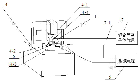
[0018] Specific implementation mode one: combine figure 1 As shown, it consists of a large-caliber plasma torch 1, a medium-caliber plasma torch 2, a small-caliber plasma torch 3, a five-axis linkage CNC machine tool 4, a radio frequency power supply 5, and a mixed plasma gas source 7;
[0019] A large-diameter plasma torch 1 or a medium-diameter plasma torch 2 or a small-diameter plasma torch 3 is installed on the insulating work frame 4-1 of the five-axis linkage CNC machine tool 4, and the large-diameter plasma torch 1 or medium-diameter plasma torch 1 or medium-diameter The plasma torch 2 or the small-diameter plasma torch 3 can be connected with the output end of the radio frequency power supply 5 as the anode of the atmospheric plasma discharge; the optical part 6 to be processed is clamped on the ground electrode 4-2, and the ground electrode 4- 2. Fixed on the horizontal motion table 4-3 of the five-axis linkage CNC machine tool 4; ground the ground electrode 4-2 as th...
specific Embodiment approach 2
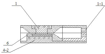
[0025] Specific implementation mode two: combination figure 2Explain that the difference between this embodiment and the specific embodiment one is that the discharge working surface of the large-diameter plasma torch 1 is a square plane or a circular plane, and its material is aluminum, and it is connected with the output end of the radio frequency power supply 5 as a The anode of the atmospheric plasma discharge is provided with an air inlet 1-1 at its side position, and the air inlet 1-1 is connected with the air outlet of the air guide hole 4-4 on the insulating work frame 4-1; when the large diameter When the plasma torch 1 is used for atmospheric plasma processing, the flow rate of the plasma gas is 2L / min-5L / min, the gas flow rate of the reaction gas is 20ml / min-90ml / min, and the ratio of the flow rate of the auxiliary gas to the reaction gas is 0 %-50%, the added RF power range is 200W-400W. Other compositions and connections are the same as in the first embodiment. ...
specific Embodiment approach 3
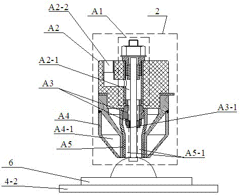
[0026] Specific implementation mode three: combination image 3 Explain that the difference between this embodiment and the first embodiment is that the plasma torch 2 with a medium diameter is composed of an inner electrode A1, a circular polytetrafluoroethylene connection block A2, a circular insulating fixing sleeve A3, a hollow circular ring Consists of external electrode A4 and circular tube ceramic nozzle A5;
[0027] The upper end surface of the circular polytetrafluoroethylene connecting block A2 is provided with an air inlet A2-2 connected with the inner hole A2-1 of the circular polytetrafluoroethylene connecting block A2, and the circular insulating fixing sleeve A3 is provided with There are a plurality of ventilation holes A3-1, and a cooling cavity A4-1 is provided inside the hollow circular outer electrode A4; the upper end of the inner electrode A1 is embedded in the inner hole A2-1 of the circular PTFE connection block A2 In the upper end, the ring-shaped ins...
PUM
 Abstract
Description
Claims
Application Information
 - R&D
- Intellectual Property
- Life Sciences
- Materials
- Tech Scout
- Unparalleled Data Quality
- Higher Quality Content
- 60% Fewer Hallucinations
Browse by: Latest US Patents, China's latest patents, Technical Efficacy Thesaurus, Application Domain, Technology Topic, Popular Technical Reports.
© 2025 PatSnap. All rights reserved.Legal|Privacy policy|Modern Slavery Act Transparency Statement|Sitemap|About US| Contact US: help@patsnap.com