Multiplexing device for multiplexing signals

A technology of multi-channel signal and multiplexing device, which is applied in the direction of multiplexing communication, time-division multiplexing system, electrical components, etc., can solve the problems of only two to four, time-consuming, and difficult connection of test probes, etc. Achieve the effect of improving test speed and ensuring synchronization

Inactive Publication Date: 2012-02-01
UNIV OF ELECTRONICS SCI & TECH OF CHINA
View PDF0 Cites 0 Cited by
  • Summary
  • Abstract
  • Description
  • Claims
  • Application Information

AI Technical Summary

Problems solved by technology

The current mixed-signal analyzers send signals from analog probes and digital probes respectively. Since there are dozens of digital channels and generally only two to four analog channels, it is necessary to observe the waveform and timing of these digital signals at the same time. It is extremely inconvenient to constantly move the analog probe to test different signals
As the integration of electronic systems becomes higher and higher, the number of signals on the bus or chips increases, and the connection of test probes becomes more difficult. It is very inconvenient and time-consuming to use several analog probes to test dozens or even hundreds of signals. lot of time

Method used


Image

  • Multiplexing device for multiplexing signals
  • Multiplexing device for multiplexing signals
  • Multiplexing device for multiplexing signals

Examples


Embodiment Construction

[0013] The following describes preferred specific embodiments of the present invention in conjunction with the accompanying drawings. It is to be noted that similar parts are given similar reference numerals even though they appear in different drawings. Also, in the following description, when a detailed description of known functions and designs employed may obscure the subject matter of the present invention, these descriptions will be omitted here.

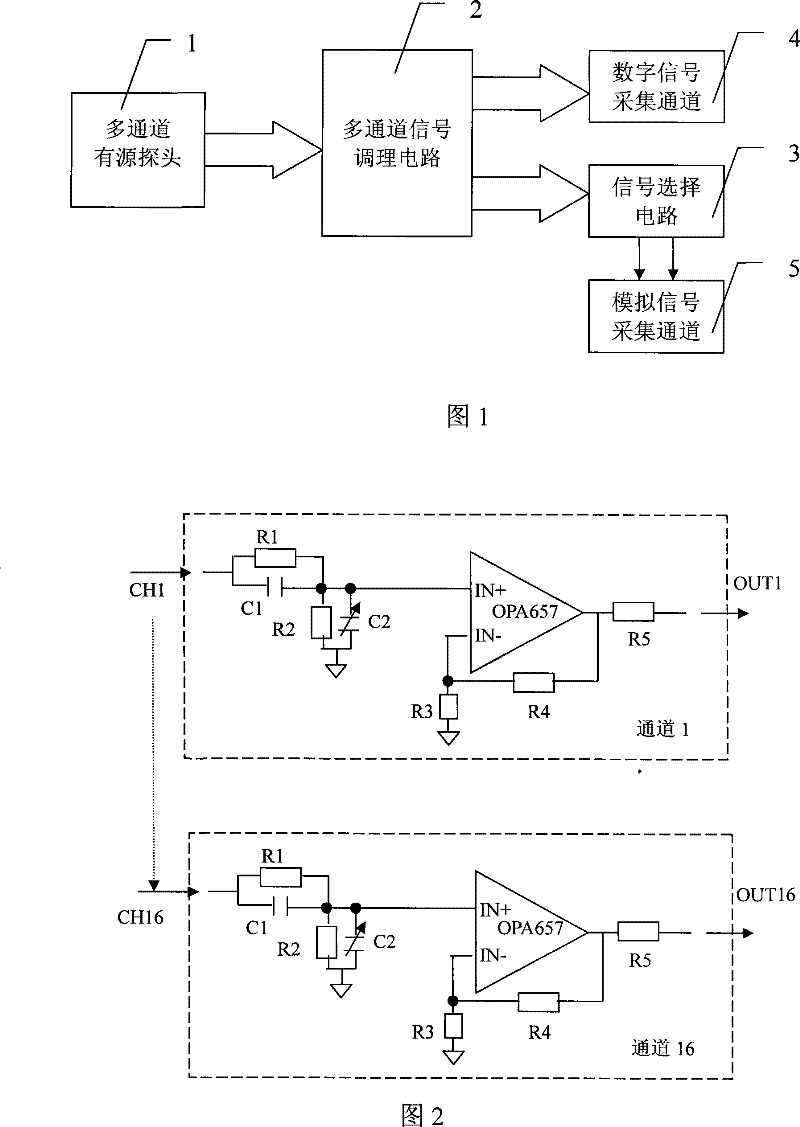
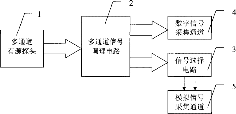
[0014] figure 1 It is a functional block diagram of the multi-channel signal multiplexing device of the present invention. In the figure, the multi-channel signal multiplexing device includes a multi-channel active probe 1, a multi-channel signal conditioning circuit 2 and a signal selection circuit 3;

[0015] The multi-channel active probe 1 sends the measured multi-channel signals to the multi-channel signal conditioning circuit 2 respectively through the signal transmission cable, and the conditioned multi-channel signal...


PUM


Abstract

The invention provides a multi-channel signal multiplexing device, which includes a multi-channel active probe, a multi-channel signal conditioning circuit and a signal selection circuit; the multi-channel active probe sends the measured multi-channel signals to the In the multi-channel signal conditioning circuit, the multi-channel signal after conditioning is divided into two groups, one group is output to the digital signal acquisition channel, and one group is output to the signal selection circuit; the signal selection circuit selects the input multi-channel signal, and the One or more signals are sent to the analog signal acquisition channel. The invention makes it possible to conveniently and synchronously observe the logic sequence and waveform of a plurality of digital signals without moving the connection position of the probe during the test, the synchronization of the signal observation can be better guaranteed, and the test speed is improved.

Description

technical field [0001] The invention relates to a multiplex signal multiplexing device. Background technique [0002] Mixed signal analysis is the main method of testing signal integrity. In the testing of high-speed digital circuits and chips, signal integrity analysis is essential. It is widely used in various electronics-related industries such as communications, consumer electronics, and semiconductor manufacturing. Applications. [0003] Mixed signal analyzers generally include two to four analog channels and more than 16 digital channels. The analog channel properly adjusts the signal and performs A / D conversion to restore its waveform; the digital channel digitizes and collects the signal to observe its timing logic. The current mixed-signal analyzers send signals from analog probes and digital probes respectively. Since there are dozens of digital channels and generally only two to four analog channels, it is necessary to observe the waveform and timing of these di...

Claims


Application Information

Patent Timeline
Patent Type & Authority Patents(China)
IPC IPC(8): H04J3/16
Inventor 戴志坚黄建国李力王厚军付在明
Owner UNIV OF ELECTRONICS SCI & TECH OF CHINA
Why Eureka
Try Eureka