Visualization debugging device for gantry machine tool

A technology for gantry machine tools and machine tools, which is applied to feeding devices, automatic control devices, metal processing machinery parts, etc., can solve the problems of prolonged workpiece processing preparation time, increased labor costs, and low efficiency, so as to eliminate the influence of human factors and improve the efficiency of The effect of knife accuracy and improving work efficiency

Active Publication Date: 2012-07-11
KEDE NUMERICAL CONTROL CO LTD
View PDF8 Cites 0 Cited by
  • Summary
  • Abstract
  • Description
  • Claims
  • Application Information

AI Technical Summary

Problems solved by technology

[0003] There are problems with this working mode in the prior art, mainly because before the machine tool starts processing, manual tool setting is required, that is, the operator needs to hold the pulse generator to complete the tool setting operation, and at the same time observe the man-machine interface of the CNC system synchronously, check Whether the knife is in place
However, in the current traditional way, two people must complete the manual tool setting operation on a large gantry machine tool. One person holds a hand-operated pulse generator on the workbench for the tool setting operation, and the other person is in front of the CNC system man-machine interface. Observe and report the tool setting position, command the tool setting operation
Since this kind of tool setting operation involves two operators, strict synchronous operation cannot be guaranteed, that is, the processing quality cannot be guaranteed, and the preparation time for workpiece processing is greatly prolonged, which not only reduces efficiency, but also increases labor costs.

Method used


Image

  • Visualization debugging device for gantry machine tool
  • Visualization debugging device for gantry machine tool
  • Visualization debugging device for gantry machine tool

Examples


Embodiment Construction

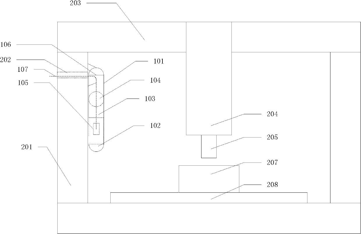
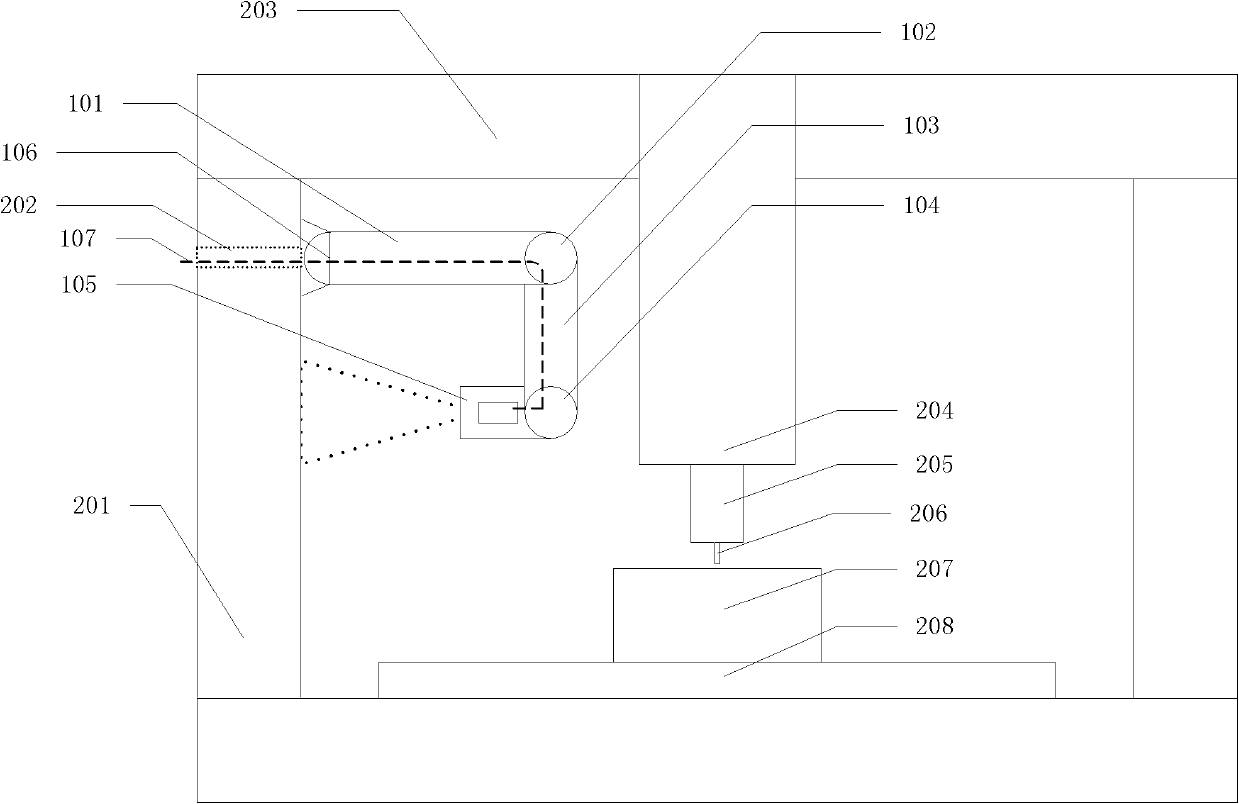
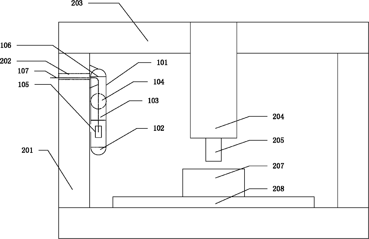
[0010] The visual debugging device of the present invention is installed on the column 201 of the machine tool that needs to be debugged, and can be stretched and contracted, which is convenient for debugging and does not affect the work of the machine tool. Such as Figure 1-2 As shown, the main frame of the gantry machine tool includes a beam 203, columns 201 are arranged at both ends of the beam 203, and a spindle box 204 is installed longitudinally in the middle of the beam, and the spindle head 205 of the spindle box protrudes from the lower end thereof, and works directly below it. Workpiece 207 on stage 208. A visual debugging device for a gantry machine tool of the present invention includes an outer casing 101, one end of the outer casing 101 is hinged and fixed on the inner side of the column 201 on one side of the machine tool through a first hinge 106, and the other end of the outer casing 101 One end of the inner bracket 103 is hinged and fixed together by the se...


PUM


Abstract

A visualization debugging device for a gantry machine tool is installed on a machine tool work table and comprises an outer casing, an inner support, hinging devices and a video playing terminal. The outer casing is installed on a machine tool vertical column through the hinging device, the inner support is connected with the outer casing through the hinging device, and the video playing terminal is connected with the inner support through the hinging device. A signal cable and a power cord required by the video playing terminal are connected to the video playing terminal through rib holes of the machine tool vertical column, the outer casing and the inner support. The other end of the signal cable is connected with a machine tool numerical control system to project a human-computer interface of the numerical control system to a machine tool debugging site, so that a work table worker can carry out synchronous observation in the cutter presetting operation process conveniently. One operator can independently finish the cutter presetting operation and check the tool presetting position, thereby avoiding the human factor influence caused by multiple-operator operation and improving cutter presetting accuracy. The video playing terminal can rotate at any angles towards any directions, thereby meeting using requirements of operators at different angles, improving work efficiency and reducing labor cost simultaneously.

Description

technical field [0001] The invention relates to a matching debugging device for a machine tool, more specifically, a visual debugging device for a gantry machine tool. Background technique [0002] Under the existing technology, due to the large size of the gantry machine tool, the distance between the workbench and the numerical control system is relatively long, and the workbench and the numerical control system are separated by a machine tool shield to ensure that the operator of the numerical control system of the machine tool is protected when the machine tool is working. Safety. [0003] There are problems with this working mode in the prior art, mainly because before the machine tool starts processing, manual tool setting is required, that is, the operator needs to hold the pulse generator to complete the tool setting operation, and at the same time observe the man-machine interface of the CNC system synchronously, check Whether the knife is in place. However, in th...

Claims


Application Information

Patent Timeline
IPC IPC(8): B23Q15/22
Inventor 陈虎于德海江世琳杜长林
Owner KEDE NUMERICAL CONTROL CO LTD
Why Eureka
Try Eureka