Supercharge Your Innovation With Domain-Expert AI Agents!

Positioning method for lead wire frame breadth direction in electroplating

A lead frame and positioning method technology, applied in the electrolytic process, electrolytic components and other directions, can solve the problems of dimensional changes, estimation and processing errors, and it takes 1 to 2 days, or even longer to adjust, etc. handy effect

Inactive Publication Date: 2008-05-28
深圳市长龙点金科技有限公司
View PDF0 Cites 3 Cited by
  • Summary
  • Abstract
  • Description
  • Claims
  • Application Information

AI Technical Summary

Problems solved by technology

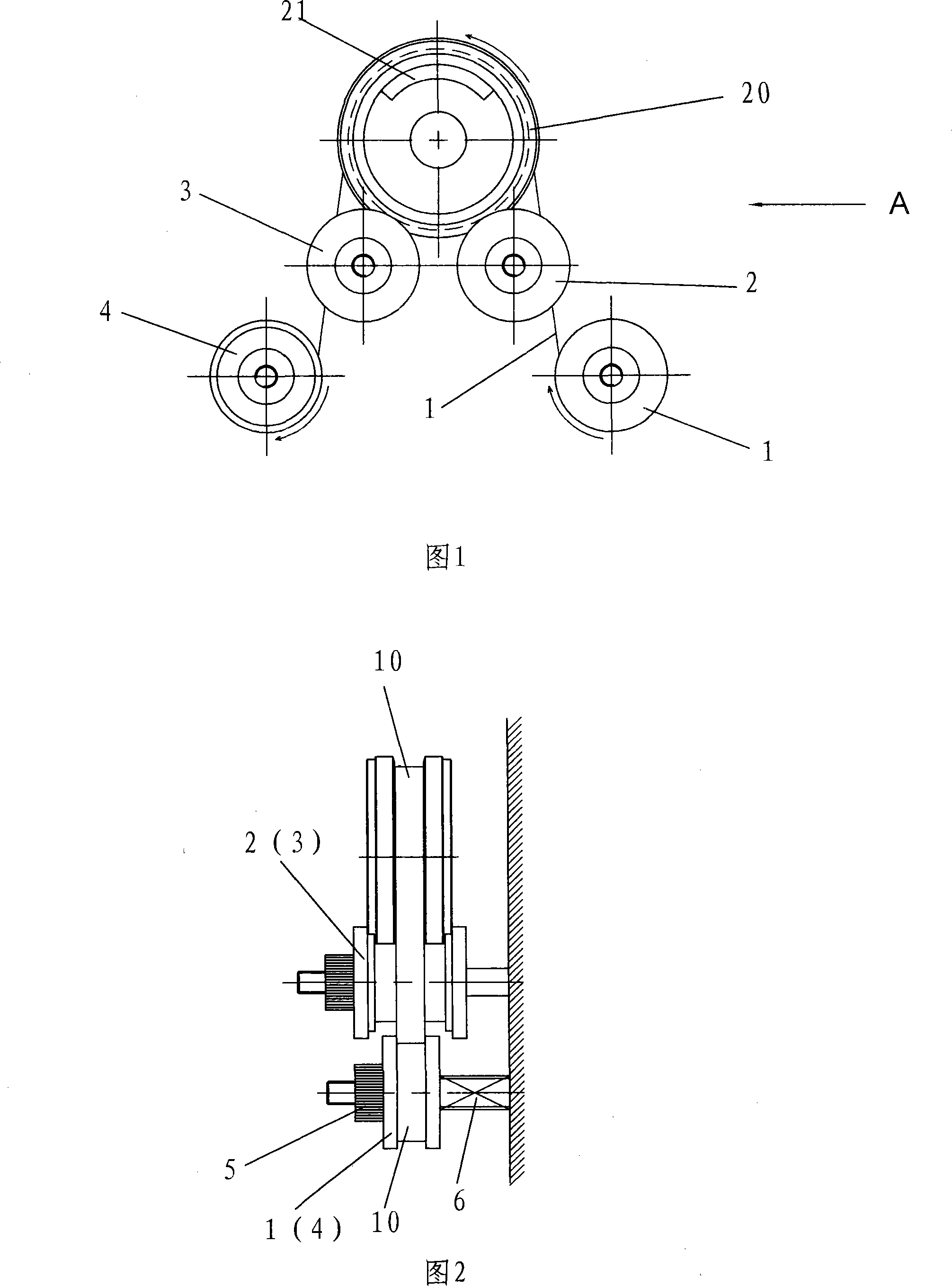
There are currently two ways to adjust the position of the lead frame 10 in the width direction, one is to adjust the guide wheel adjustment knob 5 of the front guide wheel 1 or / and the rear guide wheel 4, and cooperate with the spring 6 on the other side of the guide wheel to make the lead frame 10 Move in the width direction to achieve the correct positioning of the lead frame 10 in the width direction, but this method must rely on the experience of skilled workers to operate, even skilled workers need 1 to 2 days, or even longer time to adjust
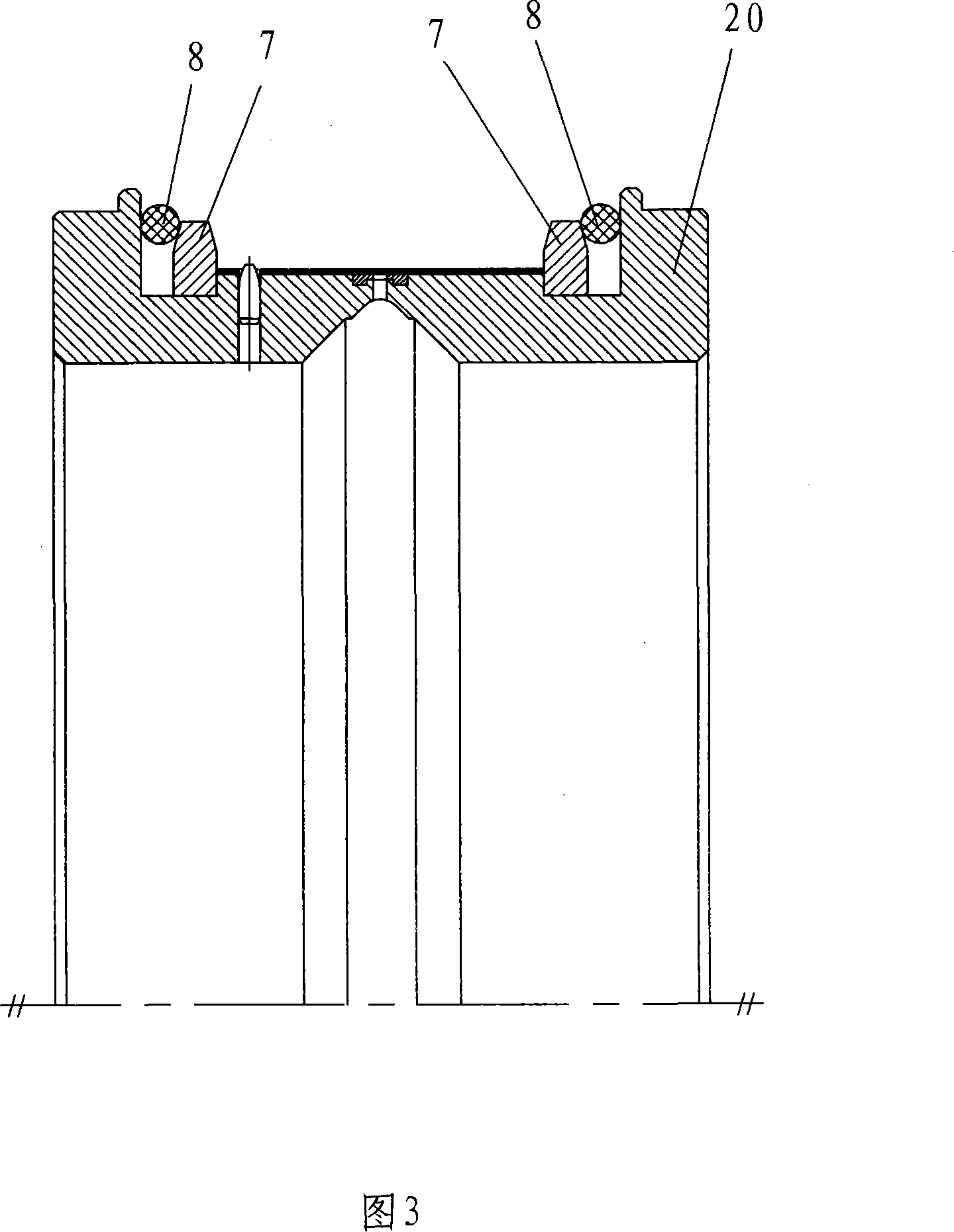
Another kind of method is to be used in the method for adding locating ring and the sealing ring of compressing locating ring on electroplating mould, and this method sees Fig. The outer side is provided with the sealing ring 8 that compresses the positioning ring, and the positioning ring is positioned close to the lead frame. The defect of this method is: the temperature of the electroplating mold 20, that is to say, the temperature of the electroplating solution is higher than room temperature, and the mold and The thermal expansion of the lead frame will lead to a change in size, and the lead frame and mold will also have a change in size when they are subjected to various forces when they are working.
There will be errors in the estimation and processing of dimensional changes, and the position of the positioning ring 7 cannot be adjusted, so once the positioning of the lead frame in the width direction is not accurate, it cannot be adjusted

Method used


Image

  • Positioning method for lead wire frame breadth direction in electroplating
  • Positioning method for lead wire frame breadth direction in electroplating
  • Positioning method for lead wire frame breadth direction in electroplating

Examples


Embodiment Construction

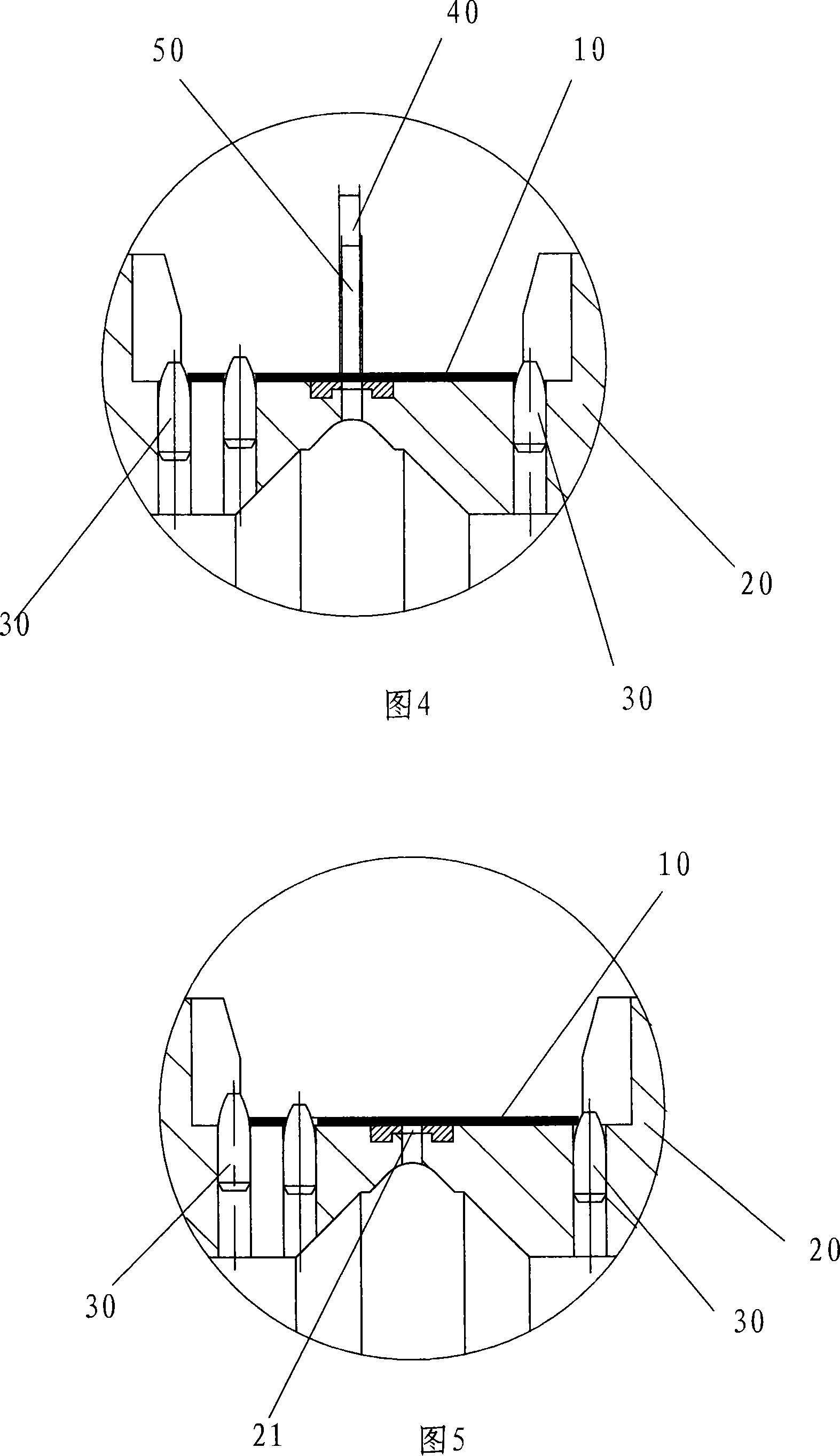
[0015] A method for positioning the width direction of the lead frame during electroplating provided by the present invention is to set a group of ceramic nails 30 on at least one side of the lead frame 10 in the width direction of the lead frame 10 on the electroplating mold 20 during electroplating. The other side of the lead frame 10 applies a pushing force to the lead frame 10 in the direction of the ceramic nail 30 , so that the lead frame 10 is close to the ceramic nail 30 .

[0016] Please refer to FIG. 4 and FIG. 5 . FIG. 4 is a schematic diagram of the principle of an implementation method of the present invention. FIG. 5 is a schematic structural diagram of FIG. 4 after adjustment. What Fig. 4 shows is that after the lead frame 10 is mounted on the electroplating mold 20, the width direction of the lead frame 10 has an error, and its ideal electroplating area 40 and the actual electroplating area 50 have deviations, and the lead frame 10 needs to be adjusted to the r...


PUM


Abstract

Disclosed is a location method which is to direction of lead frame width when electric plating. When electric plating, at the width direction of the lead frame (10) on electroplating die, a set of ceramic nail (30) is equipped at least one side of the lead frame, applying a thrust force to the lead frame in the direction of the ceramic nail at the other side of the lead frame to enable the lead frame to construct the ceramic nail firmly. The invention has the advantages of adjusting conveniently and not influencing by errors of designing and processing.

Description

technical field [0001] The invention relates to a positioning method for the width direction of a lead frame during electroplating. This method is used for selective plating of electronic product lead frames. These electronic products include ICs, LEDs, diodes, triodes, connectors, etc. Background technique [0002] A lead frame is a thin metal strip with pilot holes and areas to be plated. The electroplating of the lead frame requires selective electroplating. The so-called selective electroplating is to use the electroplating mold to expose the part of the lead frame that needs to be electroplated, and to cover the other parts that do not need to be electroplated to achieve the purpose of selective electroplating. That is to say, when the lead frame passes through the electroplating mold, the area to be electroplated on the lead frame must be accurately aligned with the corresponding hole of the electroplating mold, so that the electroplated lead frame meets the requirem...

Claims


Application Information

Patent Timeline
Patent Type & Authority Applications(China)
IPC IPC(8): C25D5/02C25D17/00
Inventor 曲悦峰
Owner 深圳市长龙点金科技有限公司
Features
  • R&D
  • Intellectual Property
  • Life Sciences
  • Materials
  • Tech Scout
  • Unparalleled Data Quality
  • Higher Quality Content
  • 60% Fewer Hallucinations
Learn More