

Positioning and real time tracing system for temperature insensitive optical fiber optical grating stress sensing train
A fiber grating and train positioning technology, which is applied in transportation and packaging, railway car body parts, vehicle route interaction equipment, etc., to achieve the effects of shortening the time between trains, improving positioning accuracy, and cheap sensitivity
- Summary
- Abstract
- Description
- Claims
- Application Information
AI Technical Summary
Problems solved by technology
Method used
Image

Examples
Embodiment 1
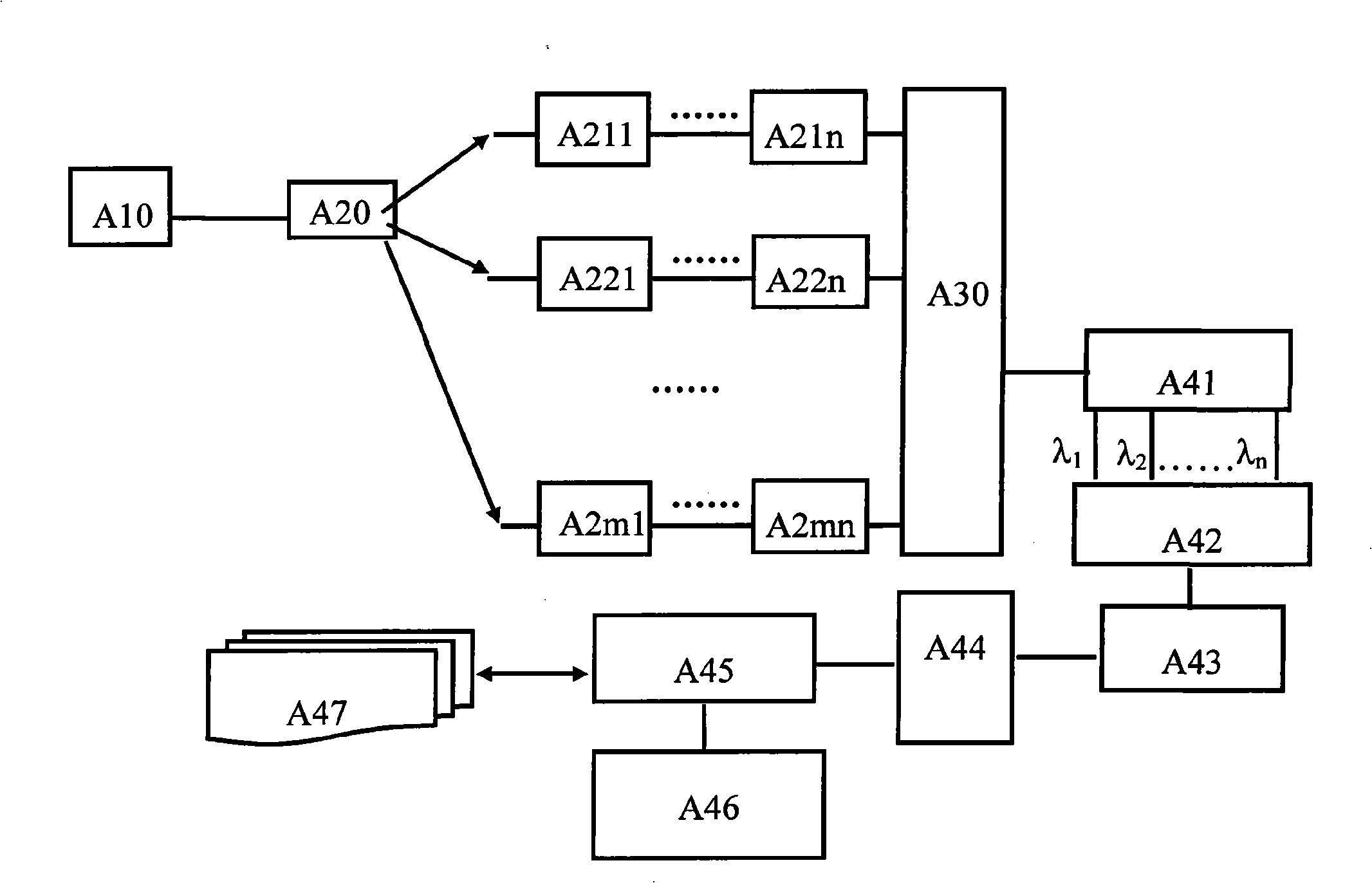
[0040] The present invention proposes a temperature-insensitive fiber grating stress sensor train positioning and real-time tracking system, the connections between the components are as follows, see image 3 :
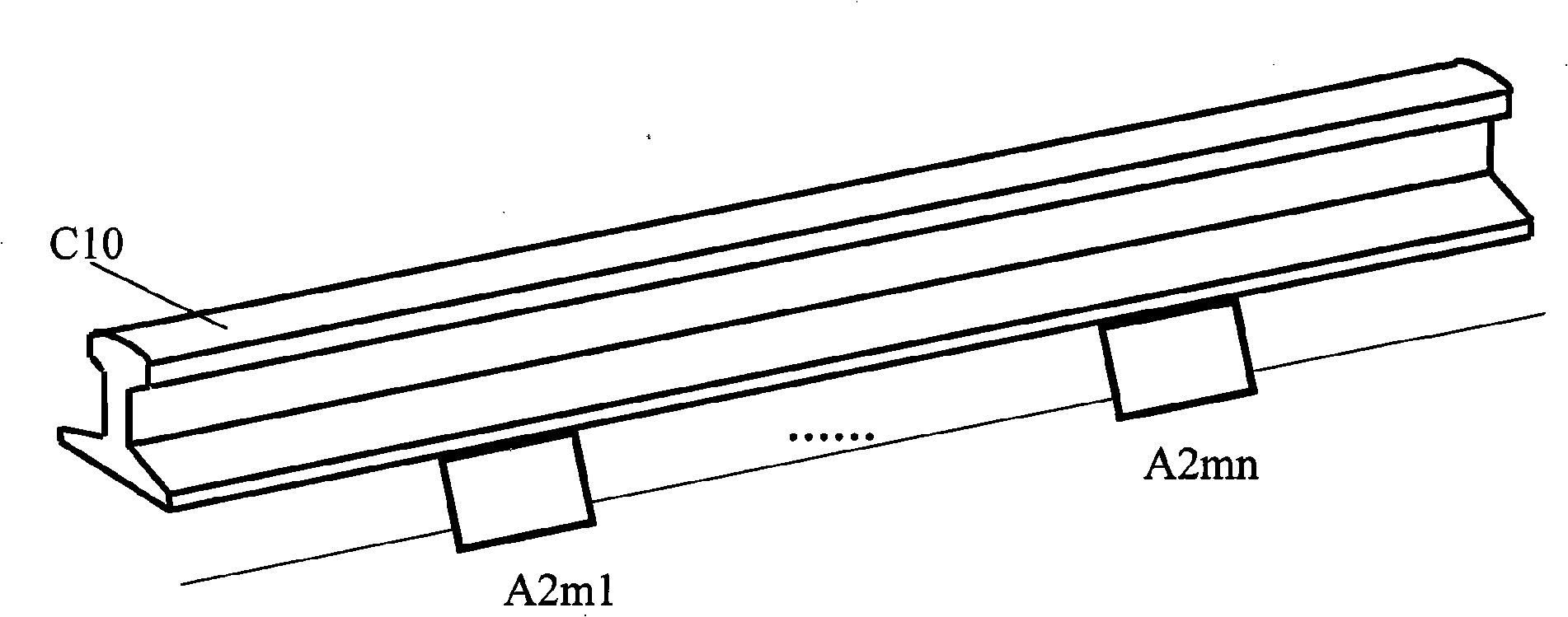
[0041] Just below a rail C10 of a railway line, fiber grating stress sensors A211...A21n are buried. The central wavelengths of these fiber grating stress sensors are different, and each fiber grating stress sensor with a different central wavelength represents a Geographic location, the upper end surface 21 of the fiber grating stress sensor is in contact with the bottom surface of the rail, the distance between two fiber grating stress sensors is 100 meters, and the connection between the adjacent two is the right port 73 of the right circulator 70 of one and the left port of the other The left port 11 of the circulator 10 is connected with an optical fiber;
[0042] The broadband light source A10 installed at the train departure station is connected to the left po...
Embodiment 2
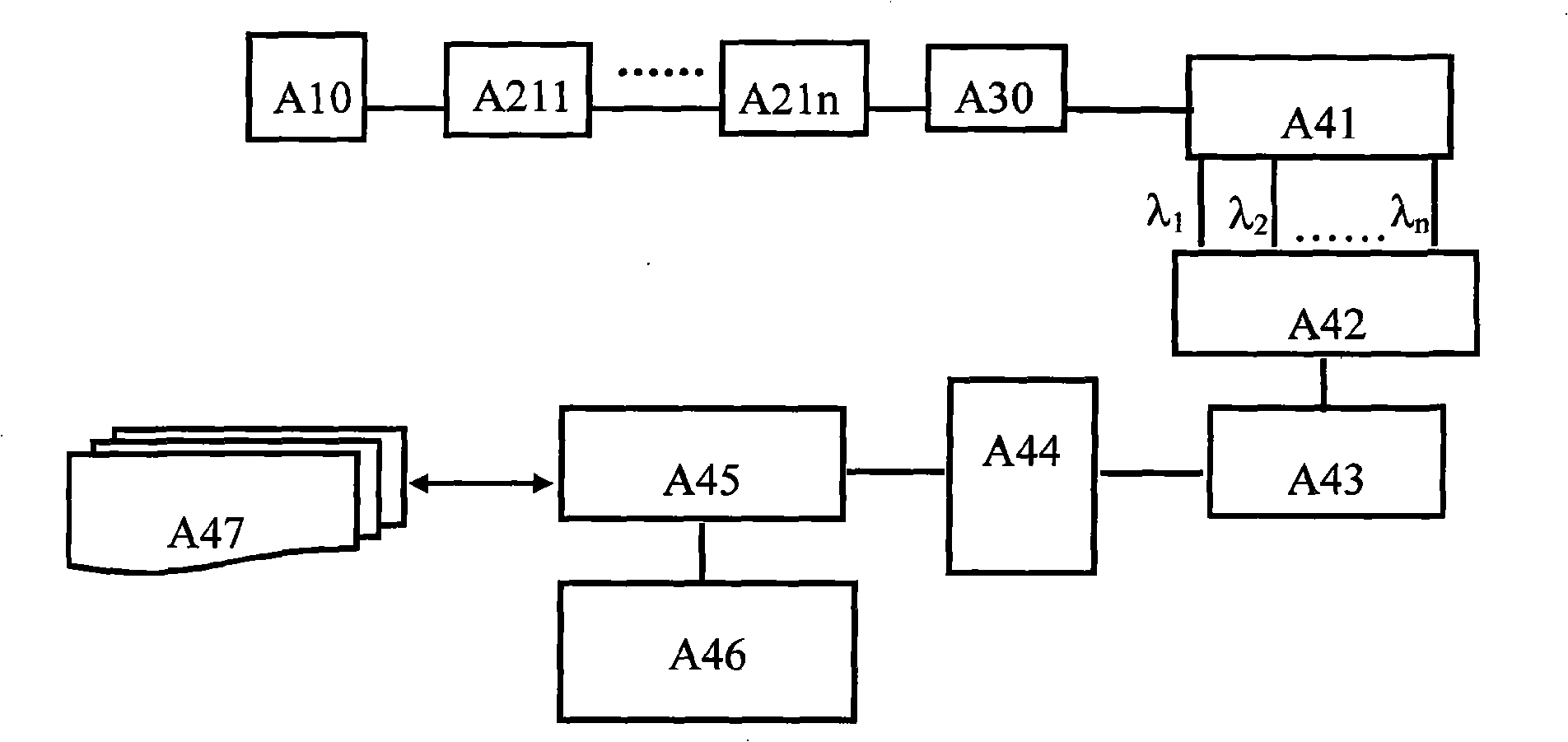
[0052] A temperature-insensitive fiber grating stress sensor train positioning and real-time tracking system proposed by the present invention, the connection between the components is as follows, see Figure 4 :
[0053] Right below each rail C10 of the two railway lines, fiber grating stress sensors A211...A21n and fiber grating stress sensors A221...A22n are buried. The central wavelengths of these fiber grating stress sensors are different. The same, each wavelength of the fiber grating stress sensor represents a geographic location, the upper end surface 21 of the fiber grating stress sensor is in contact with the bottom surface of the rail, the two fiber grating stress sensors are separated by 500 meters, and the connection between adjacent two is a right The right port 73 of the circulator 70 is connected with the left port 11 of another left circulator 10 with an optical fiber;
[0054] The broadband light source A10 installed at the departure station of the train is ...
PUM
| Property | Measurement | Unit |
|---|---|---|
| Wavelength | aaaaa | aaaaa |
Abstract
Description
Claims
Application Information