Gear mechanism for a heald shaft drive

A gear mechanism and gear technology, applied to belts/chains/gears, looms, heddles, etc., can solve problems such as different loads of two planetary gears

Inactive Publication Date: 2008-05-28
GROZ BECKERT KG
View PDF1 Cites 6 Cited by
  • Summary
  • Abstract
  • Description
  • Claims
  • Application Information

AI Technical Summary

Problems solved by technology

[0004] In this gear mechanism, different loads on the two planetary gears may result

Method used


Image

  • Gear mechanism for a heald shaft drive
  • Gear mechanism for a heald shaft drive
  • Gear mechanism for a heald shaft drive

Examples


Embodiment Construction

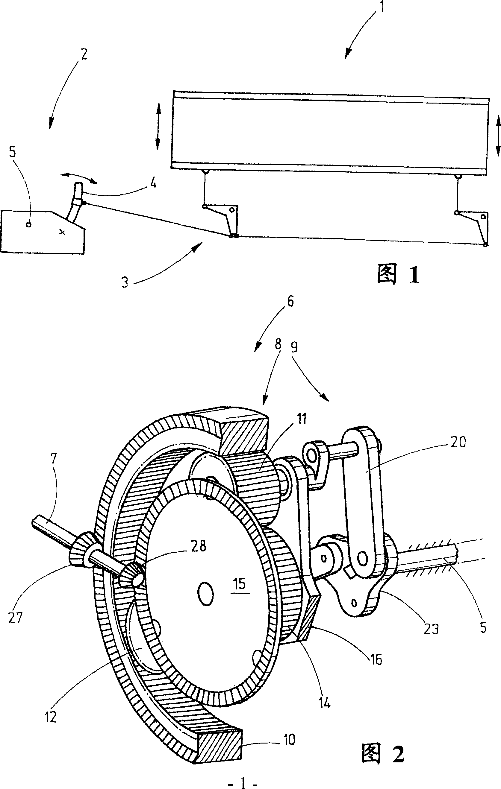
[0059] The corresponding shaft drive 2 of the heald frame 1 is shown in FIG. 1 , which, via the connecting rod 3 , brings about the vertical movement of the heald frame 1 , as indicated by the two arrows. The shaft drive 2 has a rocker arm 4 that can perform a reciprocating swinging motion. This movement comes from the rotation of the shaft 5 via, for example, an eccentric gear mechanism. If this rotation is a constant accelerated or decelerated rotary motion, then the motion of the heald frame 1 should essentially correspond to a sinusoidal motion. In this case, the sinusoidal form of the deviation, which drives the rocker arm 4 via the connecting rod 3 and the connecting rod, can be ignored. In the shaft drive according to the invention, however, the movement of the shaft 5 is not a constant rotational movement. As an alternative, the gear mechanism 6 according to FIG. 2 acting as a reduction gear produces a rotational movement on an output shaft corresponding to the shaft...


PUM


Abstract

The mechanism (6) has a planet gear (11) with an outside toothing that constantly meshes with inside toothing of a hollow gear (10), where the planet gear is rotatably positioned on a planet carrier (15). A sun gear (14) includes an outside toothing that constantly meshes with the toothing of the planet gear. A drive assembly (7) is connected to the hollow gear, planet carrier or the sun gear. An output shaft (5) is connected to the planet gear via a coupling mechanism (9). The planet gear, sun gear and the hollow gear have radii that are variable along the circumference.

Description

technical field [0001] The invention relates to gear mechanisms for heald frame drives. Background technique [0002] Weaving machines have so-called heald frames, which are formed from substantially square frames, which carry a large number of healds. The heald guides the warp thread (Kettfaden) in a targeted manner so that it moves out of the warp thread plane to form the shed (Webfach). For this, the heald frame must move up and down according to a specific setting. For this reason, it is necessary to use a so-called shaft transmission mechanism for driving, which produces an oscillating reciprocating motion when it is driven. This movement is transmitted to the heald frame via the connecting rod. The oscillating reciprocating motion of such a power take-off is usually derived from the constant rotational motion of the drive shaft. If, for example, an eccentric gear mechanism is used, then there is a predetermined relationship between the rotational movement of the in...

Claims


Application Information

Patent Timeline
Patent Type & Authority Applications(China)
IPC IPC(8): D03D51/00D03C9/06F16H37/12
CPCD03C1/00F16H2035/003Y10S475/904F16H35/02
Inventor G·波尔
Owner GROZ BECKERT KG
Why Eureka
Try Eureka