Multifunctional impact type well driller
An impact-type, multi-functional technology, applied in the direction of impact drilling, reciprocating drilling rigs, drilling equipment, etc., can solve the problems of inconvenient replacement, high construction cost, difficult and convenient positioning, etc., and achieve improved service life and high efficiency The effect of large operation and turning radius
- Summary
- Abstract
- Description
- Claims
- Application Information
AI Technical Summary
Problems solved by technology
Method used
Image
Examples
Embodiment 1
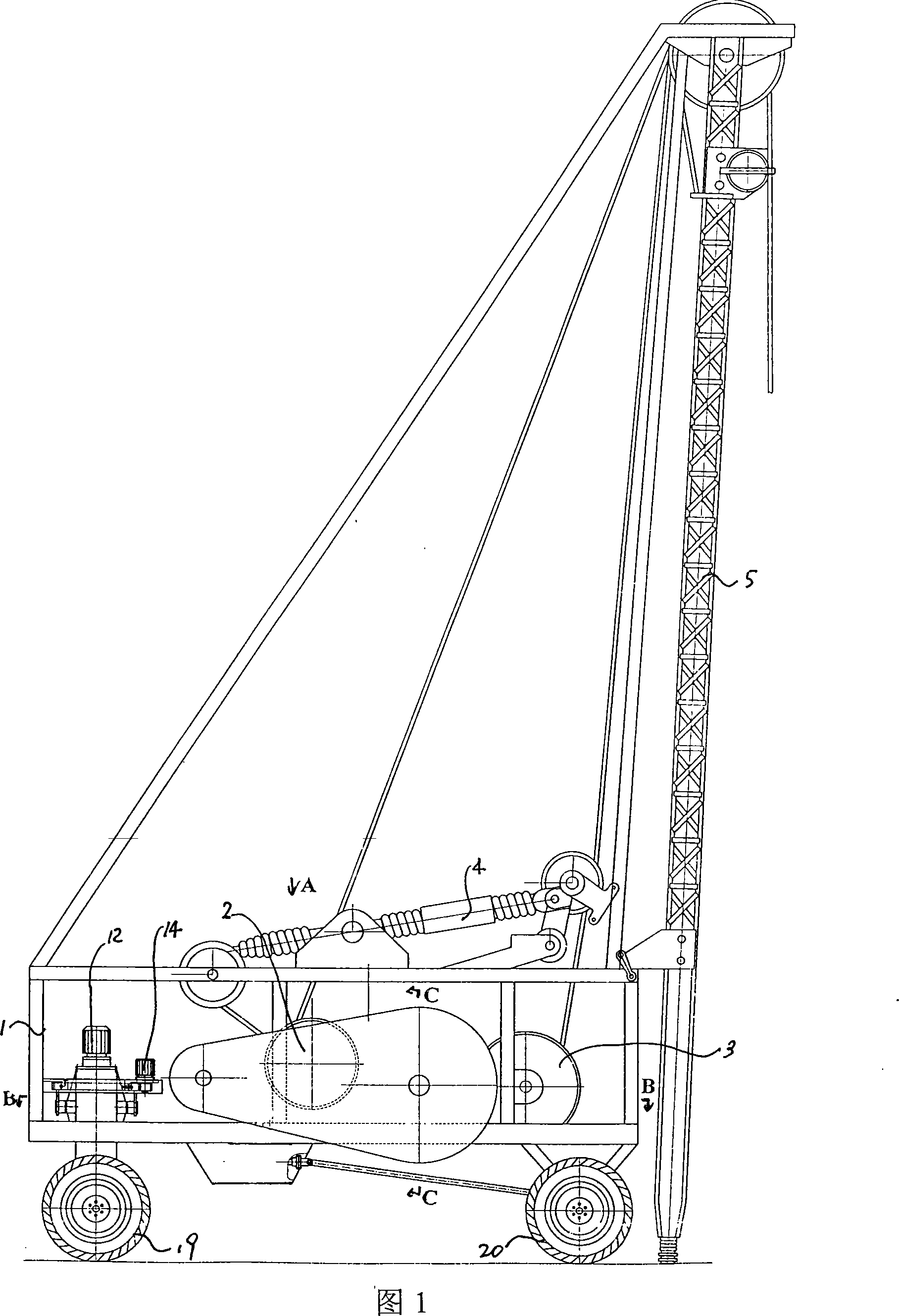
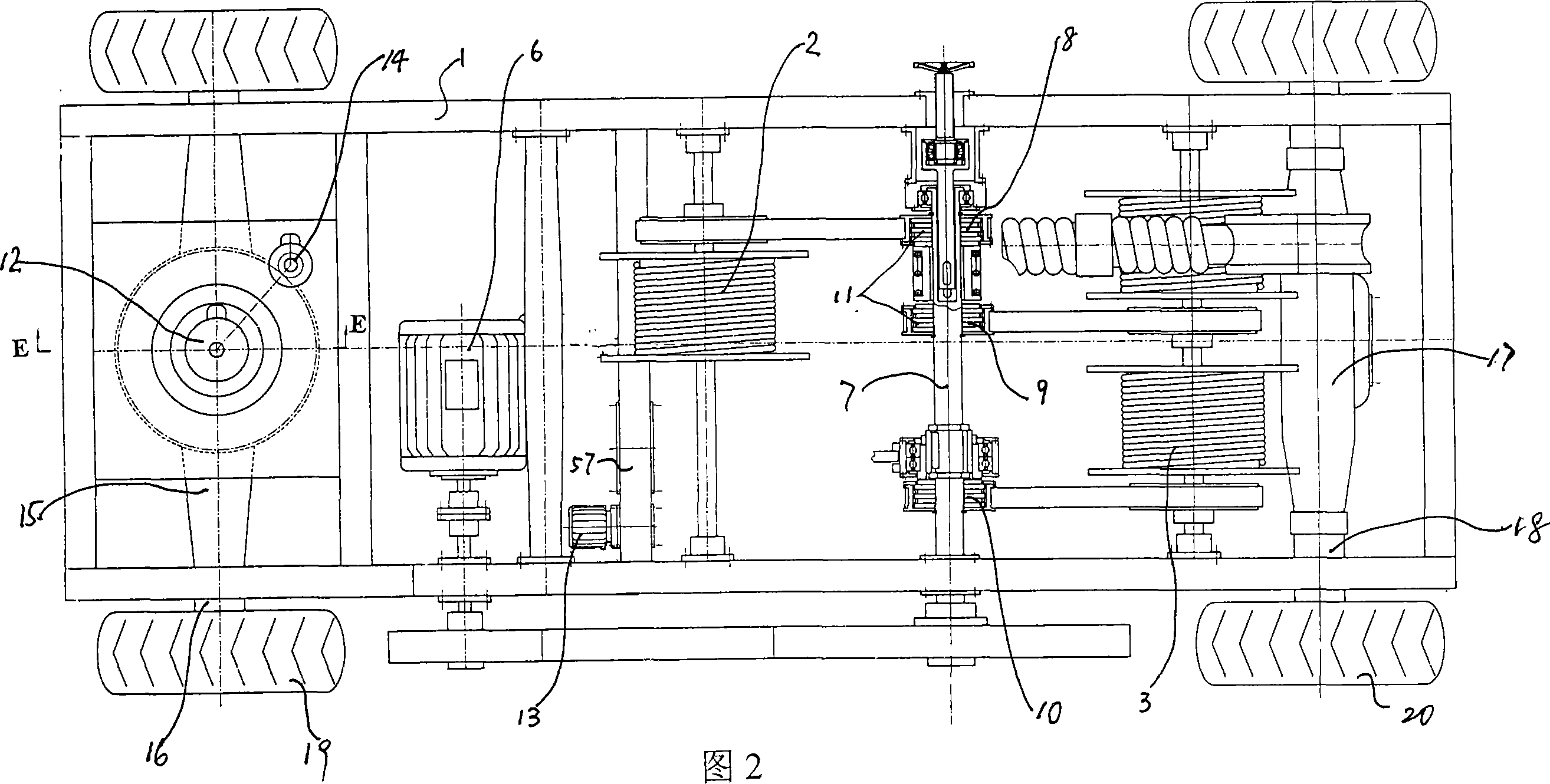
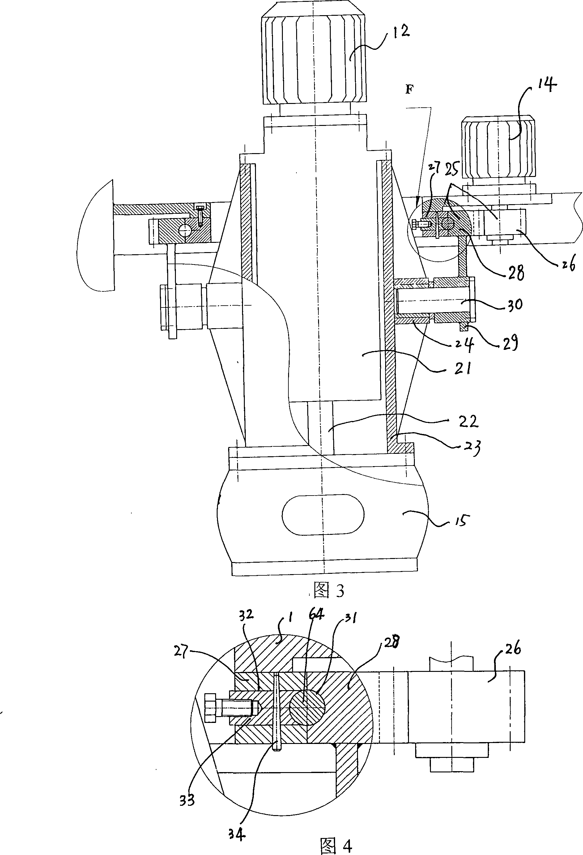
[0035] 1 to 7 show the schematic structural diagrams of Embodiment 1 of the present invention.
[0036]Referring to Figures 1 to 7, the multifunctional impact drilling machine of the present invention includes a frame 1, a main drum 2 mounted on the frame, an auxiliary drum 3, an impact beam 4, a tower frame 5, a main motor 6, including The main transmission shaft 7 driven by the main motor and the clutch assembly 11 of the main drum clutch 8, the impact gear clutch 9 and the auxiliary drum clutch 10 located on the main transmission shaft, the front wheel drive motor 12 and the rear wheel drive motor 12 are mounted on the frame. Drive motor 13, front wheel steering motor 14, the front wheel drive shaft 16 that front axle tooth bag 15 is arranged in the frame front and rear portion respectively, the rear wheel drive shaft 18 that rear axle tooth bag 17 is arranged, front wheel 19, Rear wheel 20 is contained on the front wheel drive shaft, the rear wheel drive shaft respectively...
Embodiment 2
[0039] 8 to 13 show the schematic structural diagrams of Embodiment 2 of the present invention. Embodiment 2 is basically the same as Embodiment 1. The difference is that as shown in Figures 8 to 13, a rack lifting transmission reduction mechanism 58 is installed on the frame relative to the corresponding position of the rear axle gear transmission mechanism. The power gear 59 driven by the rear wheel drive motor is arranged in the rear axle gear transmission mechanism, the power shaft 60 installed on the power gear, and the bearing sleeve 61 that is mounted on the step of an end on the power shaft and the step on the power shaft contacts, is contained in The intermediate driving gear 62 on the bearing sleeve, the driven gear 63 engaged with the intermediate driving gear mounted on the output shaft of the rear wheel, the output shaft 72 mounted on the driven gear, and the corresponding positions on the frame relative to the rear axle gear transmission mechanism Equipped with ...
PUM
 Abstract
Description
Claims
Application Information
 - R&D
- Intellectual Property
- Life Sciences
- Materials
- Tech Scout
- Unparalleled Data Quality
- Higher Quality Content
- 60% Fewer Hallucinations
Browse by: Latest US Patents, China's latest patents, Technical Efficacy Thesaurus, Application Domain, Technology Topic, Popular Technical Reports.
© 2025 PatSnap. All rights reserved.Legal|Privacy policy|Modern Slavery Act Transparency Statement|Sitemap|About US| Contact US: help@patsnap.com


