Lower positioned camshaft type engine decompression device

A technology of decompression mechanism and camshaft, which is applied in the directions of engine components, machines/engines, valve devices, etc., can solve the problems of high production and processing costs, many normal work links, and many power transmission links, etc., to achieve decompression power transmission. Stable and reliable, low production cost, easy processing

Inactive Publication Date: 2008-05-28
CHONGQING LONCIN MOTOR
View PDF0 Cites 6 Cited by
  • Summary
  • Abstract
  • Description
  • Claims
  • Application Information

AI Technical Summary

Problems solved by technology

This decompression device is composed of sliders, shift forks, pin shafts, bell cranks and other components. Not only is the structure complex, but also there are many power transmission links for decompression, so there are many links that may affect its normal work. Due to the large number of components, the production and processing costs are relatively high

Method used


Image

  • Lower positioned camshaft type engine decompression device
  • Lower positioned camshaft type engine decompression device
  • Lower positioned camshaft type engine decompression device

Examples


Embodiment Construction

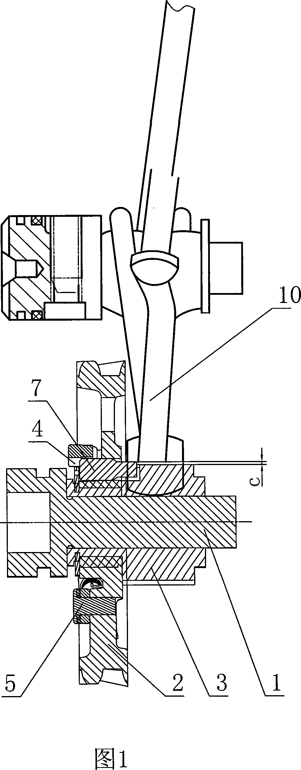
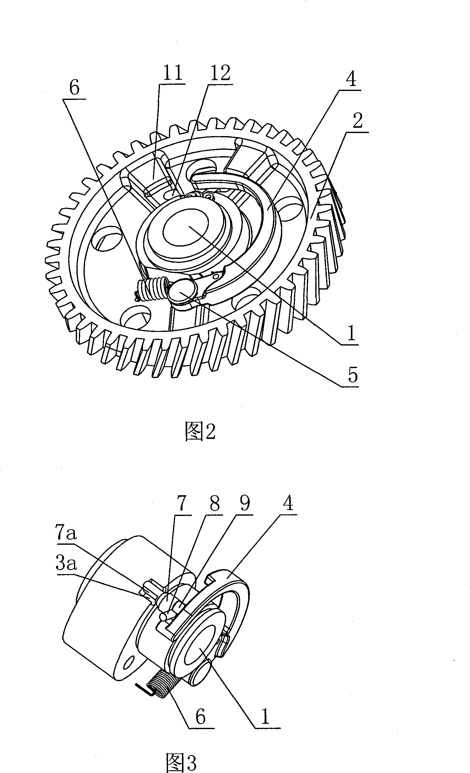
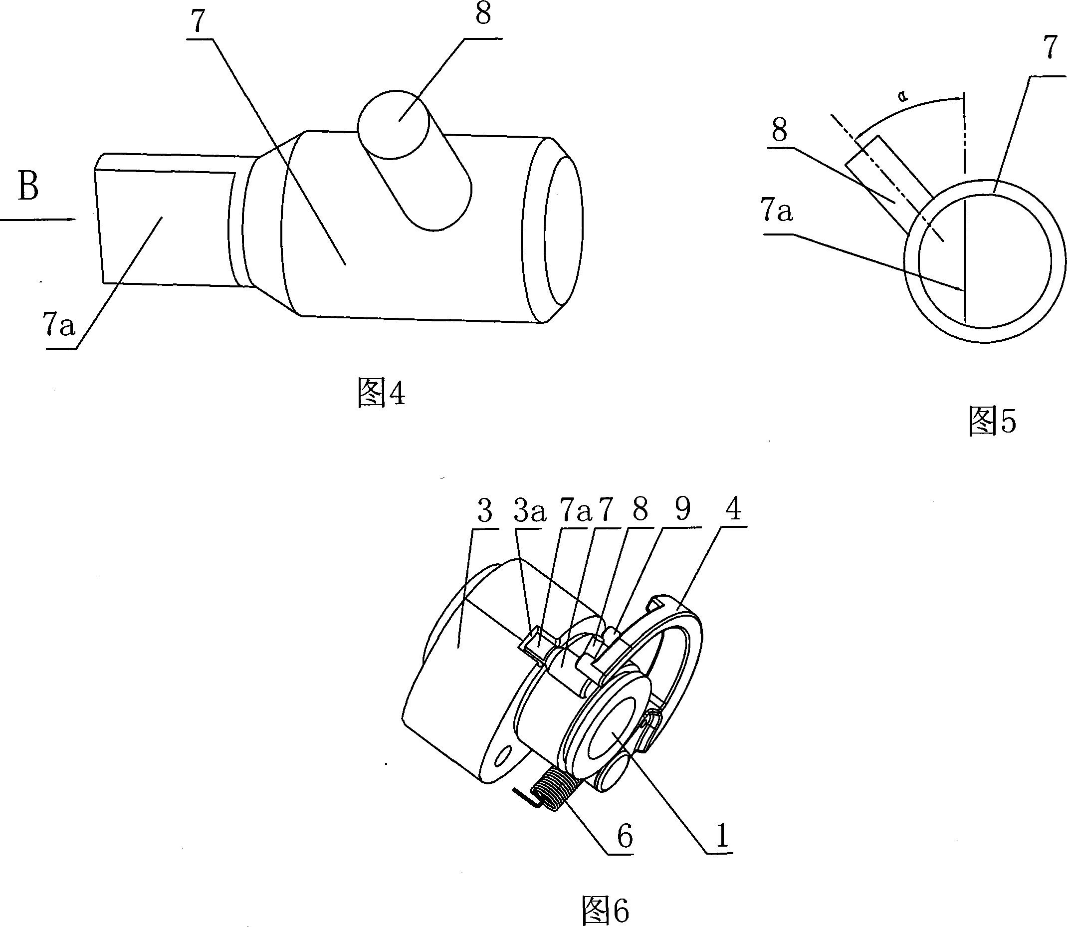
[0015] Referring to FIGS. 1 to 6 , the timing gear 2 of the lower camshaft engine is circumferentially fixed on the lower camshaft 1 and is adjacent to the exhaust cam 3 . An arc-shaped centrifugal block 4 is located on the axial end face of the timing gear 2, the fixed point end of the centrifugal block 4 is hinged with the timing gear 2, and the centrifugal block 4 is rotatably riveted and fixed on the timing gear 2 by a cylindrical pin 5 to form a hinge, and the centrifugal The free end of block 4 walks around the lower camshaft 1 and is opposite to the fixed point end. A return spring 6 is connected to the centrifugal block 4 and the timing gear 2. The return spring 6 is a tension spring, one end of which is connected to the crank arm of the centrifugal block 4 near the fixed point, and the other end is connected to the timing gear 2 at the Opposite direction of centrifugal motion. The axial end surface of the timing gear 2 is provided with a plurality of reinforcing ribs...


PUM


Abstract

The invention discloses a decompressing mechanism of a lower camshaft type motor. An eccentric block is hinged on a timing gear, a return spring is connected on the eccentric block and the timing gear, the axial direction gap of the timing gear is engaged in interval with a wheel shaft for decompressing, one end of the wheel shaft is inserted in a gap groove which is arranged on the initial point of an exhaust cam, and can rotate, the section of the one end of the wheel shaft which is inserted in the gap groove of the exhaust cam is a bow shape, and the diameter of the end is larger than the height of the gap groove, the distance between the string of the bow shape from arc top portion is smaller than the height of the gap groove, the other end of the wheel shaft is provided with a radial pin, an included angle of 30 degrees to 60 degrees is formed by the axial center line of the pin and the string plane of the bow shape, and the radial pin is inserted in a fork which is positioned on the free end of the eccentric block. With the simple structure, the motor can be effectively decompressed when being started, and the decompressing power can be stably and reliably transferred, and the producing cost can be reduced.

Description

technical field [0001] The invention relates to a decompression mechanism of an engine, in particular to a decompression mechanism of a lower camshaft engine of a motorcycle. Background technique [0002] After the displacement of the recoil-started motorcycle engine is increased, and the transmission power and torque are increased, the engine can form a large impact force during the starting process, which is easy to damage the electric starter, kick start and other devices, especially the kick start process. It is easy to cause injury to the operator. Therefore, in order to make the engine start more smoothly, a device is generally installed on the engine to reduce the cylinder pressure when the engine starts, so as to ensure the smooth start of the engine. The device that is used to reduce the cylinder pressure when the engine starts at present mainly adopts a slide block that can slide and displace on the timing driven gear connected to the camshaft. Two rivets on the d...

Claims


Application Information

Patent Timeline
IPC IPC(8): F01L13/08
Inventor 高勇李世瑛李毅
Owner CHONGQING LONCIN MOTOR
Why Eureka
Try Eureka