Hydraulic damper without idle course

A hydraulic damper and air travel technology, which is applied in the direction of gas-hydraulic shock absorber, shock absorber, shock absorber, etc., can solve the problems of poor shock absorption, short service life, spring leaf breakout, etc., and achieve improved shock absorption performance , improve the service life, and improve the effect of rebound performance

Inactive Publication Date: 2008-05-28
JIANGYIN HUAHONG QIANGSHUN TECH
View PDF0 Cites 6 Cited by
  • Summary
  • Abstract
  • Description
  • Claims
  • Application Information

AI Technical Summary

Problems solved by technology

[0004] 1. Poor shock absorption
[0005] During the reset process of the piston rod, the volume occupied by the piston rod will leave a cavity in the first working chamber, which is filled by the gas phase in the hydraulic fluid, and when the piston rod is pushed by an external force to slide the piston in the inner cylinder , the rapid movement of the piston in the cavity in the second working chamber produces an empty space, which causes vibration and gives people a feeling of landing, causing great discomfort to the driver, which will greatly weaken the shock absorption performance of the hydraulic damper
[0006] 2. Short service life
[0007] During the frequent reciprocating movement of the piston, the two sets of spring sheets on both sides of the piston are often easily broken by the hydraulic fluid with a large impact force, which will affect the service life of the hydraulic damper
[0008] 3. Poor heat dissipation
[0010] 4. High material cost
[0011] The cylinder body of the hydraulic damper adopts a double-tube structure, and a return spring is added, which is not only bulky, but also requires a lot of materials and high material costs
[0012] 5. The amplitude cannot be precisely controlled
[0013] The one-way valve on the piston is composed of a spring plate and a liquid guide hole, which cannot accurately control the flow rate of the hydraulic fluid between the two working chambers of the cylinder, and cannot accurately control the amplitude of the damper

Method used


Image

  • Hydraulic damper without idle course
  • Hydraulic damper without idle course

Examples


Embodiment Construction

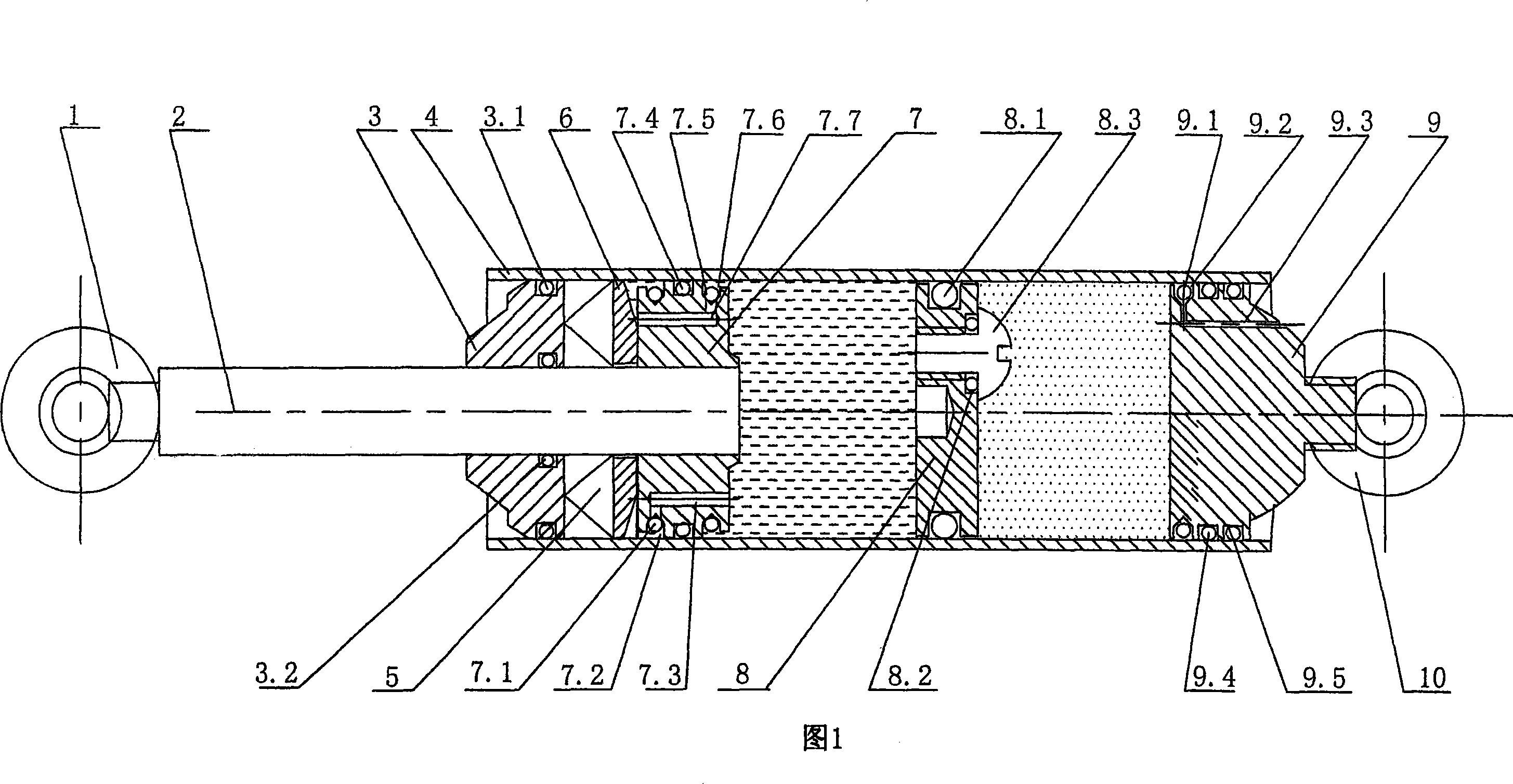
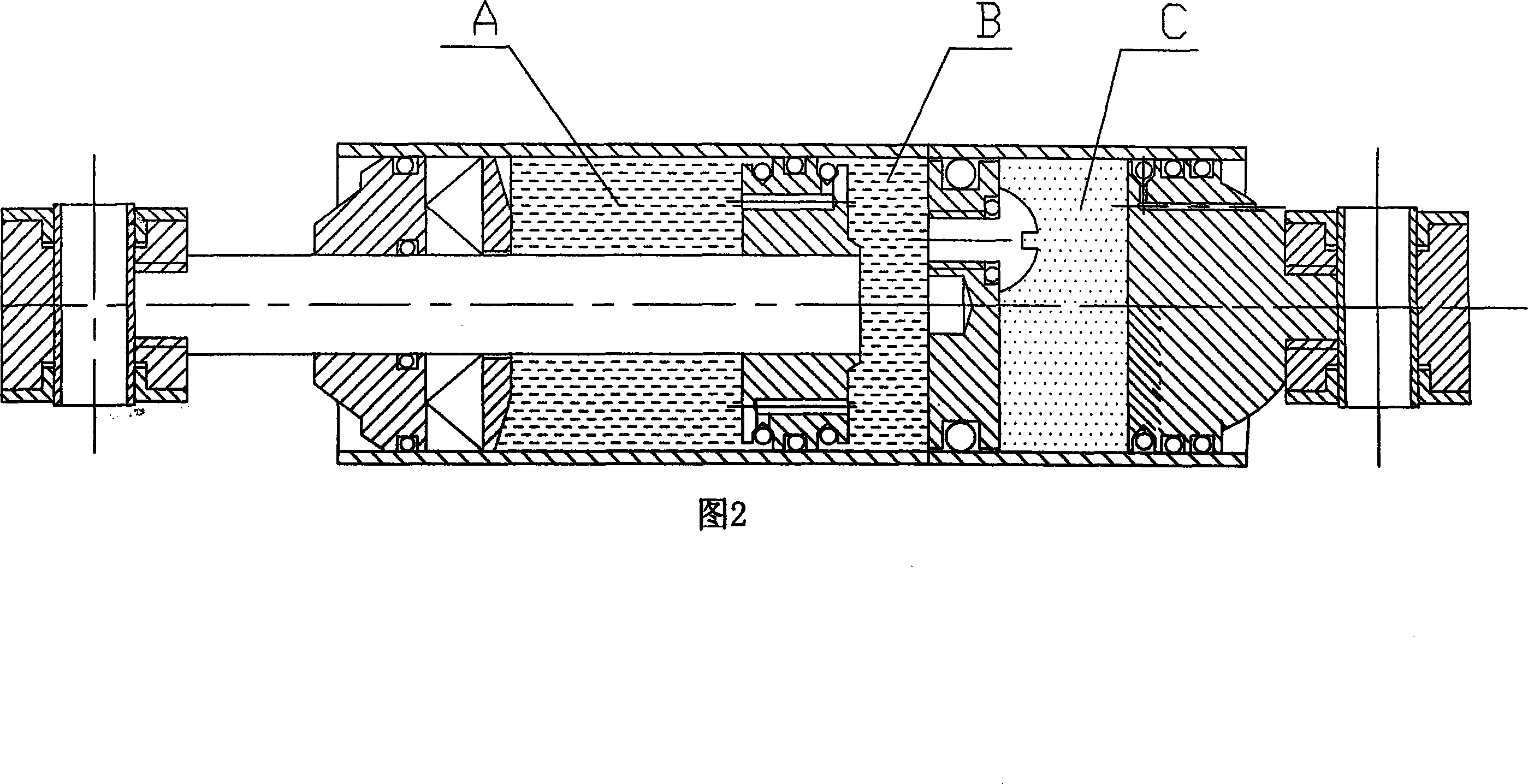
[0031] Referring to Fig. 1, the present invention relates to a hydraulic damper without lost motion, the damper has a closed cylinder 4, the inner chamber of the cylinder 4 is through a piston 7 which can slide in the cylinder and another piston which can slide in the cylinder The floating ring 8 sliding in the cylinder is divided into a first working chamber A, a second working chamber B and a third working chamber C, wherein the first working chamber A and a second working chamber B are separated by a piston and controlled by a Filled with a hydraulic fluid, the third working chamber C is filled with a gas under pressure, and the third working chamber is between the floating ring and the plug and filled with a gas with pressure.

[0032] A sealing ring IV7.4 is embedded in the middle of the outer edge of the piston 7 . A ring groove I7.2 is provided on the outer edge of the piston 7 close to the side of the first working chamber A, and a sealing ring III7.1 is embedded in th...


PUM


Abstract

The invention relates to a hydraulic damper without idle stroke, which comprises an enclosed cylinder body (4). A piston (7) which can slide in the cylinder body and a piston rod (2) which is connected with the piston are arranged in the inner chamber of the cylinder body (4). The invention is characterized in that the inner chamber of the cylinder body (4) is further provided with a floating-ring (8) which can slide in the cylinder body, the inner chamber of the cylinder body (4) is separated into a first working chamber (A), a second working chamber (B), and a third working chamber (C) by the piston (7) and the floating-ring (8), the piston rod (2) is penetrated through the first working chamber (A) and is conducted hermetically from one end of the cylinder body (4), the other end of the cylinder body (4) is provided with a plug (9), the first working chamber (A) and the second working chamber (B) are separated by the piston and are fed with hydraulic liquid, and the third working chamber (C) is positioned between the floating-ring (8) and the plug (9) and is fed with air with pressure intensity. The invention has the advantages of no idle stroke, long service life, excellent radiation, low costs of material, and controlled amplitude precision and the like.

Description

technical field [0001] The invention relates to a hydraulic damper, which is connected between a structure to be protected (such as the body of a motor vehicle) and an external disturbance source (such as a wheel in direct contact with the ground), capable of using the viscous flow of hydraulic fluid in the damper to Dissipates shock energy from external sources of disturbance. It belongs to the technical field of sealed pneumatic metal hardware. Background technique [0002] A traditional hydraulic damper has a cylinder, a piston that slides within the cylinder, and a piston rod attached to the piston, which is surrounded by a return spring. The cylinder body is a double cylinder structure, which is composed of an outer cylinder body and an inner cylinder body arranged coaxially. The inner and outer cylinders communicate with each other through springs and pressing pieces arranged at the end of the inner cylinder. The piston is arranged in the inner cylinder, and the pis...

Claims


Application Information

Patent Timeline
Patent Type & Authority Applications(China)
IPC IPC(8): F16F9/06F16F9/32F16F9/34F16F9/36
Inventor 卫德义
Owner JIANGYIN HUAHONG QIANGSHUN TECH
Why Eureka
Try Eureka