Temperature control base for measuring semiconductor light-emitting device

A technology of light-emitting devices and semiconductors, which is applied in the direction of single semiconductor device testing, temperature control, and measuring devices. It can solve problems that affect injection, cannot be constant, and affect test accuracy, and achieve accurate test results, good sealing effects, and water vapor reduction. Effect

Inactive Publication Date: 2008-05-28
HANGZHOU ZHEJIANG UNIV SENSING INSTR
View PDF0 Cites 18 Cited by
  • Summary
  • Abstract
  • Description
  • Claims
  • Application Information

AI Technical Summary

Problems solved by technology

The base body without temperature control function cannot keep the junction temperature of the tested piece relatively constant, and the test results are not comparable; the base body with temperature control function generally does not h

Method used


Image

  • Temperature control base for measuring semiconductor light-emitting device

Examples


Example Embodiment

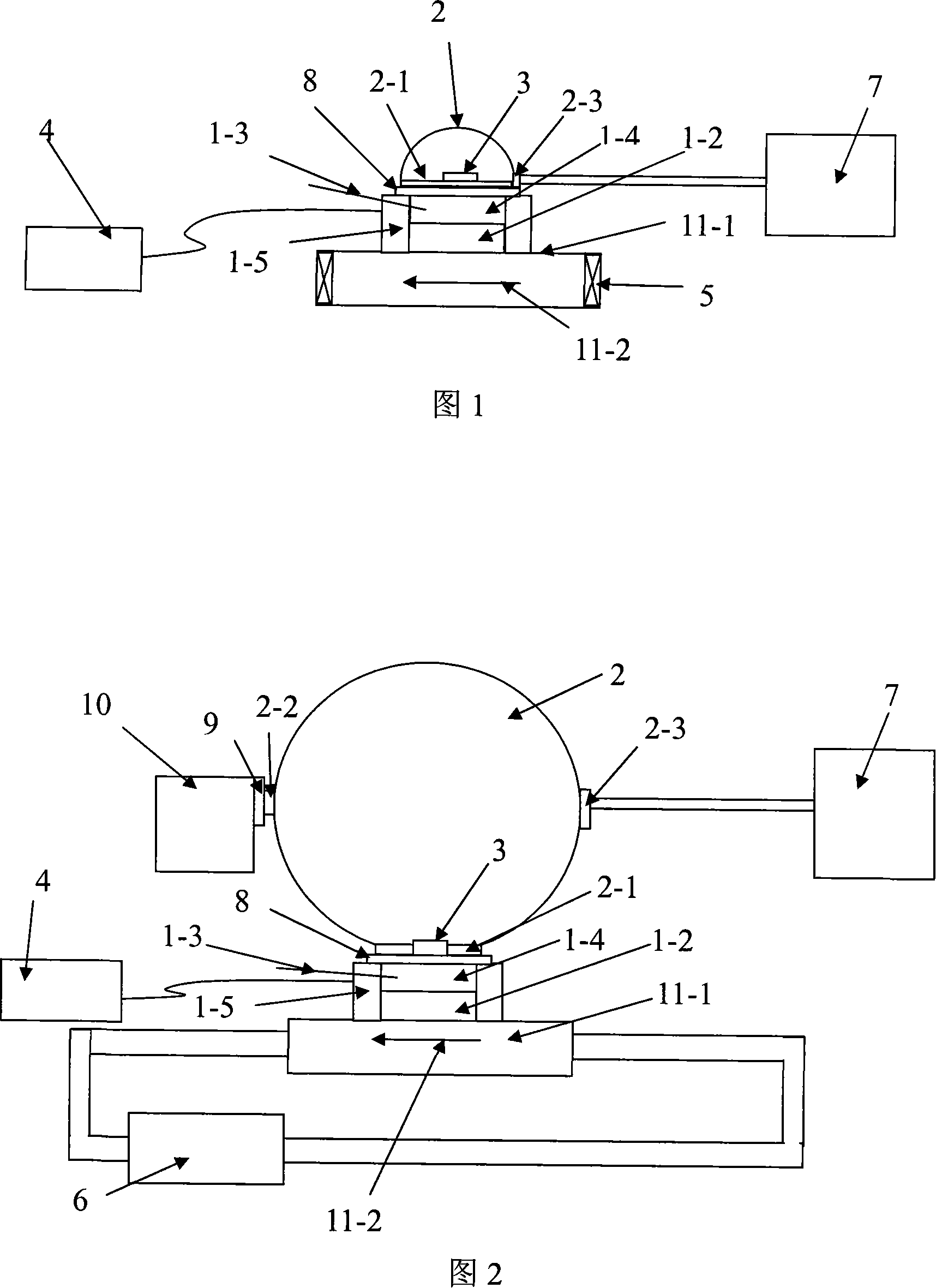
[0020] Embodiment 1: The temperature control seat for measuring semiconductor light-emitting devices, as shown in Figure 1, it can be matched with the tested part 3 and the light measuring device 10. It includes a temperature control device and a sealing cover matched with the temperature control device 2. The test piece 3 can be placed in the sealing cover 2 to cooperate with the temperature control device.

[0021] The temperature control device includes a heat dissipation device, temperature measurement elements 1-3, a temperature control element 1-2 matched with the heat dissipation device, a thermostatic seat 1-4 matched with the temperature control element 1-2, a thermostatic seat 1-4 and a temperature control element The exposed part of 1-2 is covered with a heat-insulating layer 1-5, the heat-insulating layer 1-5 is provided with a placement opening for the tested piece 3, and the tested piece 3 can be installed on the thermostatic seat 1-4 through the placement opening. T...

Example Embodiment

[0025] Embodiment 2: The temperature control seat for measuring semiconductor light-emitting devices, as shown in Figure 2. On the temperature control seat, the sealing cover 2 is a photometric integrating sphere, and the opening 2-1 matched with the thermostat seat 1-4 It is located on the wall below the sphere and on the cut surface of the sphere, and the tested object 3 is located in the center of the opening 2-1. There is a test port 2-2 on the side wall of the sphere. A light transmission channel 9 is installed on the test port 2-2. The outer end of the light transmission channel 9 is connected to a light measuring device. The light measuring device can be with a detector or with light. Transmitter's photometric instrument 10.

[0026] The heat dissipation device includes a heat dissipation base 11-1, a convection cavity 11-2 arranged on the heat dissipation base 11-1, a power pump 6 matched with the convection cavity 11-2, and the convection cavity 11-2 can pass gas or liqui...


PUM


Abstract

The invention relates to a temperature controlling base for testing semi-conductive illuminant device, which is provided with temperature controlling function and avoids condensation of moisture. The invention comprises a temperature controlling device and a seal closure which is matched with the temperature controlling device, wherein testing specimens can be arranged into the seal closure and matched with the temperature controlling device. The distinguishing progresses of the invention are that the testing specimens is located in a comparative constant temperature status through an arrangement of the temperature controlling device, testing results are accurate, the testing specimens are separated form around circumstance through the arrangement of the seal closure, thereby effects of the around circumstance can be avoided, sealing effects of the seal closure is better through the arrangement of seal components, the arrangement of an extraction opening enables that a vacuum machine is connected with the seal closure through the extraction opening, air inside the seal closure can be extracted, vapor can be decreased, the vapor can be avoided to condense on the testing specimens.

Description

【Technical Field】 [0001] The invention relates to a measuring device, in particular to a temperature control seat for measuring a semiconductor light emitting device with a temperature control function and condensation prevention. 【Background technique】 [0002] The core of the semiconductor light-emitting device is the PN junction, and the temperature of the PN junction is called the junction temperature. The performance of semiconductor light-emitting devices is related to the junction temperature, and the photoelectric color parameters of semiconductor light-emitting devices at different junction temperatures are different. Therefore, to correctly test and evaluate the photoelectric color parameters of the semiconductor light-emitting device, the temperature of the semiconductor light-emitting device must be controlled to keep it relatively constant. [0003] The prior art holders for measuring semiconductor light-emitting devices are divided into two types with a temperature ...

Claims


Application Information

Patent Timeline
IPC IPC(8): G01R31/26G01J1/00G05D23/00
Inventor 牟同升
Owner HANGZHOU ZHEJIANG UNIV SENSING INSTR
Why Eureka
Try Eureka