Damage-free detection archeological method

A non-destructive detection and detection method technology, applied in the field of archaeological detection, can solve problems such as comprehensive interpretation and analysis of difficult detection data, unfavorable protection and excavation of archaeological cultural relics, low efficiency of information management and research utilization, etc.

Inactive Publication Date: 2008-05-28
CHENGDU UNIVERSITY OF TECHNOLOGY
View PDF0 Cites 7 Cited by
  • Summary
  • Abstract
  • Description
  • Claims
  • Application Information

AI Technical Summary

Problems solved by technology

However, due to the diverse characteristics of non-destructive detection archaeological methods, ranging from small-scale ground-penetrating radar detection, high-density resistivity detection, high-precision magnetic detection, induced polarization detection to large-scale remote sensing detection, etc., involve a wide range of fields. The detection data is multi-source, multi-dimensional, and multi-scale, so various detection data and processing results are likely to form information islands, and multiple methods cannot be integrated to confirm and restrain each other, resulting in many drawbacks in data management and processing, and it is difficult to realize Comprehensive interpretation and analysis of detection data, thereby reducing the effective utilization of detection information
[0004] Therefore, the existing archaeological methods have low efficiency in information management and research utilization, which is not conducive to comprehensive consideration and comparison of data obtained by various detection methods, and is not conducive to obtaining more accurate relic outline and internal structure information. Conservation and excavation work disadvantageous

Method used


Image

  • Damage-free detection archeological method
  • Damage-free detection archeological method

Examples


Embodiment Construction

[0021] The present invention will be further described below in conjunction with the drawings and embodiments.

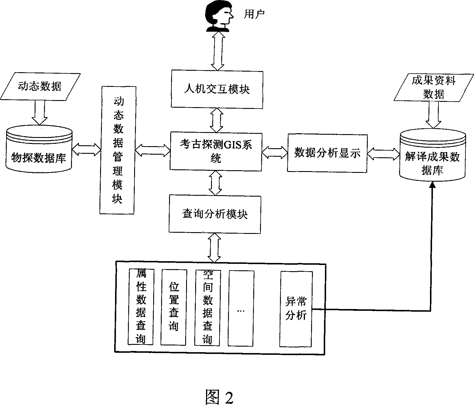
[0022] A non-destructive exploration archeology method, the system adopted is shown in Figure 2.

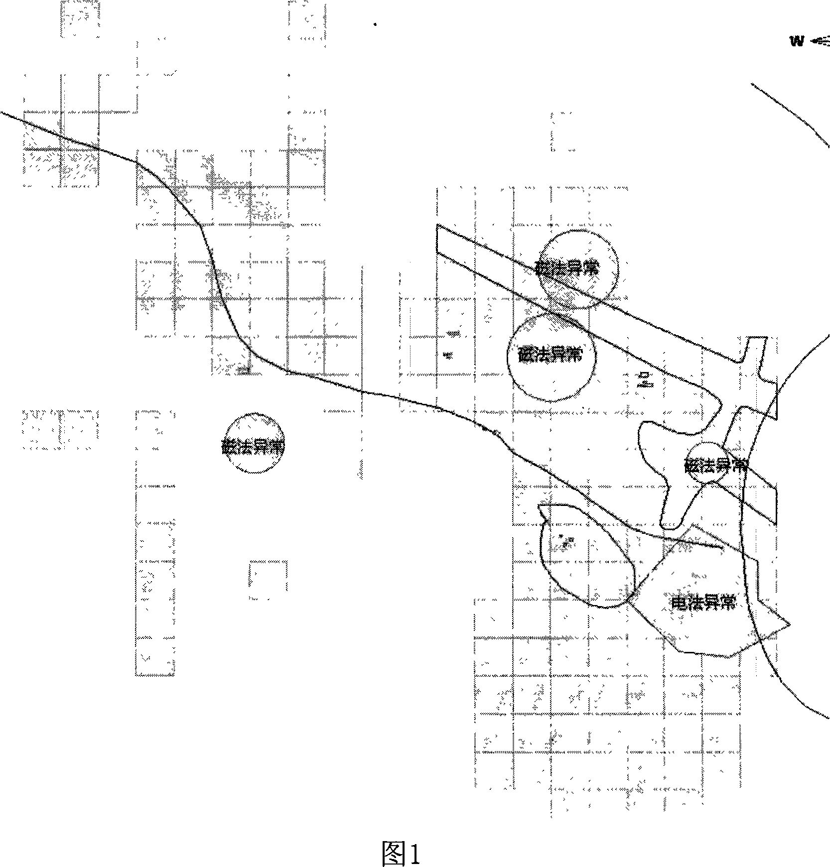
[0023] First, use ground penetrating radar detection, high-density resistivity detection, high-precision magnetic detection, induced polarization detection, remote sensing detection and other methods to detect the relics that need to be detected. Then the collected data are sorted and input into the computer. The collected data includes The plane coordinates projected in the vertical direction of the measured point and the geophysical properties value of the same depth in this direction.

[0024] The characteristics of some of these detection methods are as follows:

[0025] In principle, the high-density resistivity detection method belongs to the category of the resistivity method. It is based on the electrical difference of rock and soil to study the change and distribu...


PUM


Abstract

The invention discloses a nondestructive detection archaeology method, which comprises gathering geographic information data and geophysical prospecting property value of archaeological sites through a plurality of nondestructive detection technologies, dividing the geophysical prospecting property value of detection points into different data range segments to mark different colors, generating a drawing layer by interpolation, creating corresponding drawing layers with different detection methods in order, preserving the created drawing layers to a database, analyzing detection points in a same drawing layer, and a detection point whose property value exceeds the reservation normal range is an abnormal point, stacking the selected drawing layers and then outputting according to the selection of a user, getting the geographical position and the contour of the archaeological site by the image processing and the fuzzy recognition. By analyzing and replicating the gathered data of a plurality of archaeology methods, the method generates an intuitive chart, which can realize delineation and the definition of abnormality of cultural relics accurately through the comparing and analyzing of the detection data, and can represent the burying situation of the underground cultural relics without disinterring the archaeological sites, thereby establishing a base for the restoration of the archaeological sites and the protection of the cultural relic.

Description

Technical field [0001] The invention relates to an archaeological detection method, in particular to a non-destructive detection archaeology method that combines geophysical detection technology and information management technology. Background technique [0002] The excavation of archaeological sites often requires several phased excavations to complete, which has a certain long-term nature, and the content of each excavation needs to be added to the distribution map of the relics in time. Therefore, in addition to the excavation records, the excavation data of the ruins are usually supplemented and revised on the existing map or the actual survey map each time the exploration and excavation work is over, and new ruins or phenomena are added. As a result, the data of a ruins will gradually increase. Moreover, because some data can be used in the archaeological research of geographic information systems, it can exist on one or several maps of the distribution of sites in differen...

Claims


Application Information

Patent Timeline
Patent Type & Authority Applications(China)
IPC IPC(8): G06F17/00G06F17/30G06T11/00G01V3/00G01S17/89
Inventor 王绪本李海蓉曹礼刚郑文锋
Owner CHENGDU UNIVERSITY OF TECHNOLOGY
Why Eureka
Try Eureka