Remote control location method and system

A positioning method and positioning system technology, applied in the field of remote control, can solve the problems of limited functions, complicated cursor movement operation, unfriendly human-computer interaction interface, etc., and achieve the effect of convenient operation, low cost, and friendly human-computer interface

Inactive Publication Date: 2008-05-28
SICHUAN CHANGHONG ELECTRIC CO LTD
View PDF0 Cites 4 Cited by
  • Summary
  • Abstract
  • Description
  • Claims
  • Application Information

AI Technical Summary

Problems solved by technology

But corresponding to this, compared with computers, the human-computer interaction interface of smart home appliances is not friendly, the cursor movement operation is complicated, and the realized functions are limited.
Currently, only limited functionality is available via the four-way cursor keys on the remote

Method used


Image

  • Remote control location method and system
  • Remote control location method and system
  • Remote control location method and system

Examples


Embodiment Construction

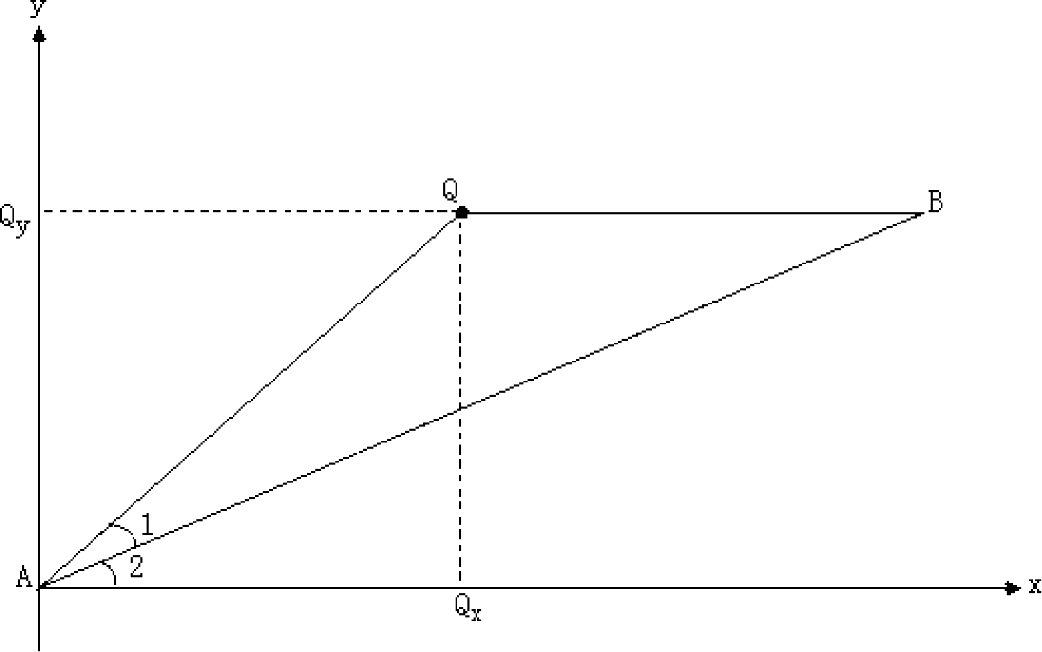
[0031] In the field of remote control technology, the carrier of the remote control signal is generally radio wave, visible light, laser, etc., and the more commonly used ones are radio wave and infrared light. In a specific embodiment of the present invention, infrared light is used as the carrier of the remote control signal. In the implementation process, the emitted light of the remote control is regarded as a point light source, and the position of the remote control signal on the plane is the spatial coordinate of the remote control signal on the plane, that is, the center point of the remote control signal is on the projection point of the plane, and the normal line of the remote control signal is the remote control signal. The straight line between the projection point of the signal on the plane and the emission point.

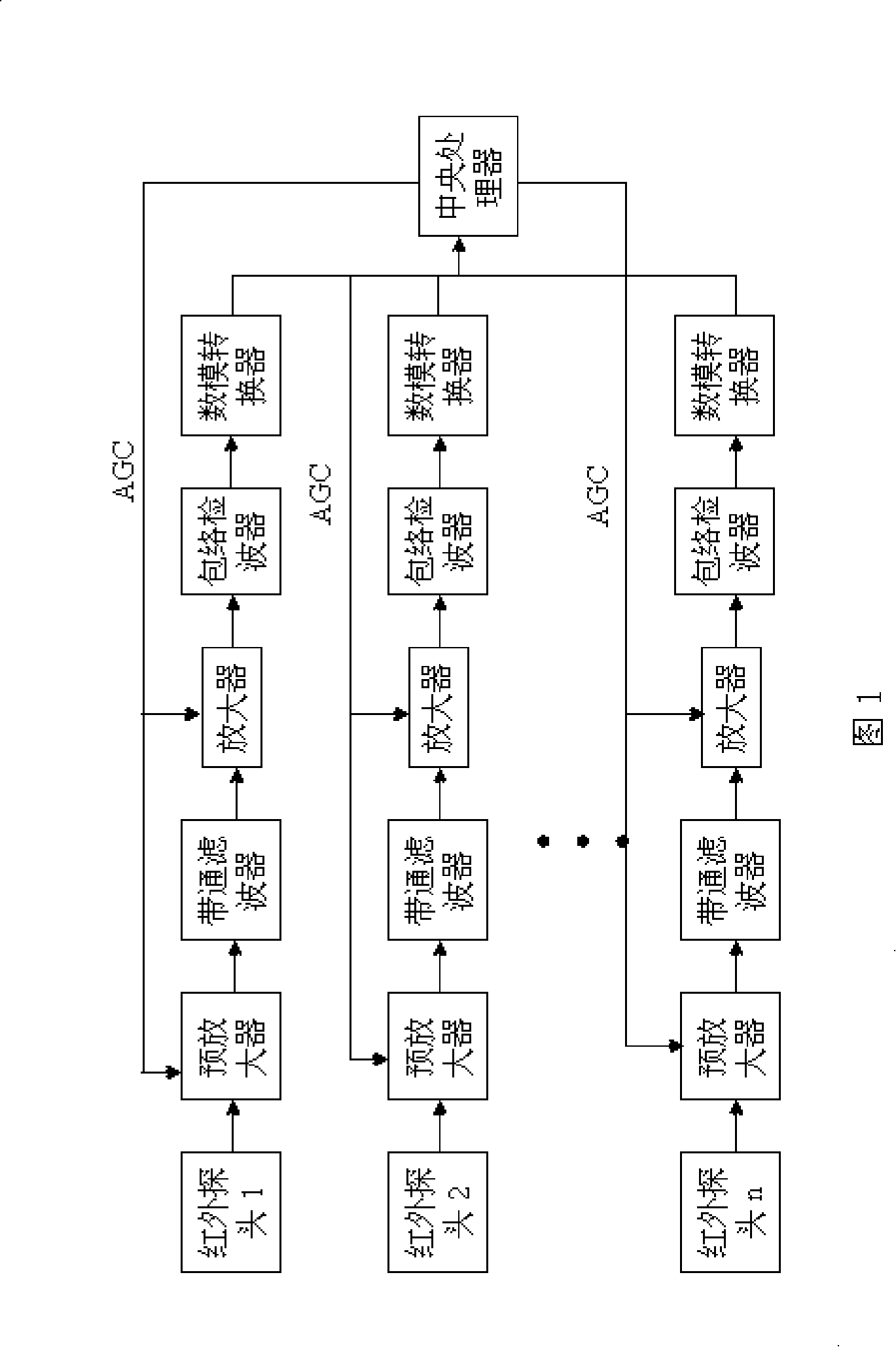
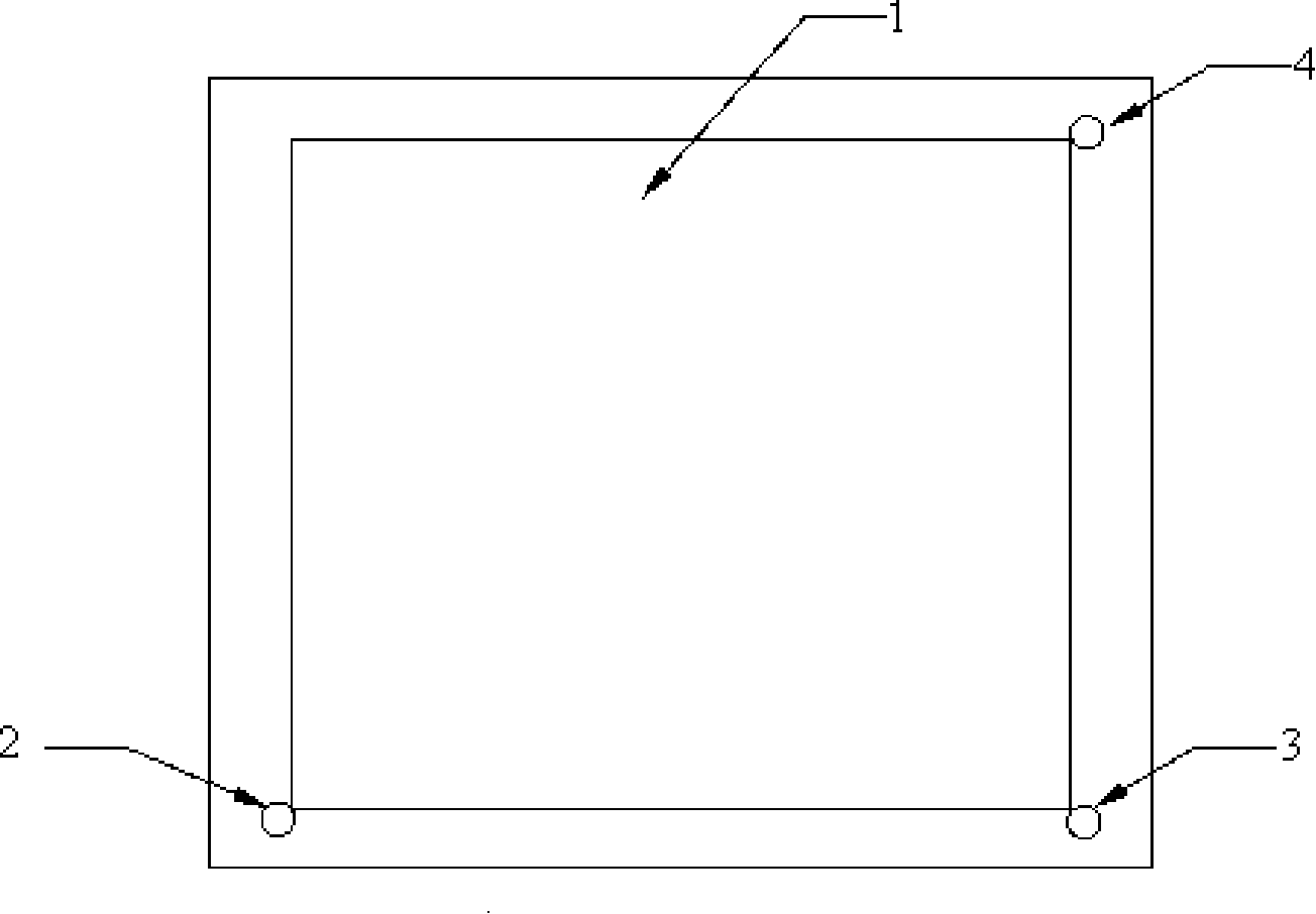
[0032] See Figure 1, set at least 2 infrared probes around the screen of the remote control receiving device, such as a TV, to receive the infrared si...


PUM


Abstract

The invention relates to the telecontrol technology, in particular to a technology which can realize the cursor location through detecting the movement of the remote control signals. The telecontrol location method of the invention is that telecontrol signal intensities of different points in a panel can be detected; the space coordinates of telecontrol signal can be worked out according to the position relationships of points and signal intensities. The telecontrol location system of the invention comprises a controlled screen, a remote control, at least two signal probes of the remote control, a signal processing circuit and a central processing unit. The signal probes of the remote control are arranged around the controlled screen and connected with the signal processing circuit which is connected with the central processing unit. The invention has the beneficial effects that the remote control has the functions of a mobile cursor and provides a friendly man-machine interchanging platform between household appliances and users; in addition, the invention has a low cost.

Description

technical field [0001] The invention relates to remote control technology, in particular to a technology for realizing cursor positioning by detecting the movement of remote control signals. Background technique [0002] At present, in the field of screen display remote control technology of electronic products, the remote control sends remote control commands to the receiver through the optical carrier (such as infrared rays, etc.) through the transmitter, and the receiver then converts the received remote control information through light and electricity. Send it to the application coding / decoding ASIC chip for demodulation and decoding, so as to realize the corresponding remote control operation. With the rapid development of smart home appliances, their functions are becoming more and more powerful, and they begin to realize and replace some computer functions, such as browsing the Internet, sending and receiving emails, etc. But corresponding to this, compared with com...

Claims


Application Information

Patent Timeline
Patent Type & Authority Applications(China)
IPC IPC(8): G08C23/04
Inventor 贾汇东吴楚宁
Owner SICHUAN CHANGHONG ELECTRIC CO LTD
Why Eureka
Try Eureka